Pneumatic Grain Elevators have been employed with good effect in loading and unloading grain from ships. This method of conveying grain falls under three systems: (1) the blast system; (2) the suction system; and (3) the combined blast and suction
system.
In the first system a barge, known as a machinery barge, is fitted with a steam boiler, a set of air compressing engines, and a length of flexible piping long enough to reach from any part of the barge to the farthest corner of the ship to be loaded. A small pipe, known as the nozzle, is inserted at the inlet end of the piping, where the grain is taken in, and communicates with the air compressor at the other end. Compressed air can be admitted to the nozzle or shut off by a valve. The inlet end of the flexible pipe is pushed into the grain in the barge, while the other end is led over the hatches of the vessel to be loaded. As the compressor is set to work and the valve of the compressed air supply pipe opened, the air naturally rushes up the pipe and escapes at the other end which is lying over the ship’s hatchway. If the inlet nozzle be immersed in the grain to the depth of 12 to 18 in. the induced atmospheric air will follow the lead of the compressed air, and drawing the grain around into the inlet nozzle will carry it up the pipe and deliver it into the hold of the vessel loading.
 |
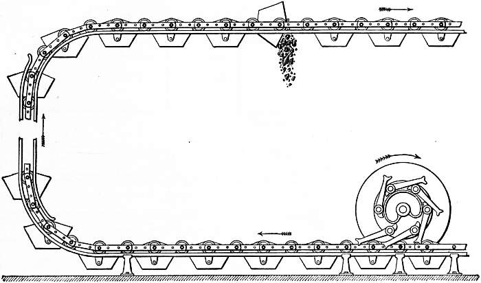
| Fig. 10.—Travelling Bucket Elevator. |
In the suction system, which is identified with the name of F. E. Duckham, the process is somewhat different. An air-tight tank or receiver, 8 to 10 ft. in diameter and 10 to 20 ft. high, is fitted with a hopper bottom, and is erected, if floating, on a barge, at a sufficient height to allow grain falling from the hopper bottom, and passing through an air lock, to be delivered by gravity through a shoot into the vessel being loaded. A pipe connects the vacuum tank with the exhaust pumps. Several flexible pipes of sufficient length to reach any corner of the ship to be unloaded, may be connected with the vacuum tank. As the air pumps are set working a partial vacuum is formed within the tank, and as the nozzle end of the pipe is immersed into the grain to the depth of a few inches, the air and grain are drawn in at the mouth of the nozzle and carried along the pipe to the vacuum tank. The natural expansion of the air then lets the grain drop to the hopper bottom, whence it issues from an air-lock valve, while the air is drawn away by a pipe communicating with the pumps and is thence discharged into the open.
In the third system, or blast and suction combined, the grain is sucked into a vacuum tank, as just described, and drops from this through valves into a second receptacle, whence it is conveyed to any desired point by flexible pipes. This second tank is divided into two sections and provided with valves so that the two sections will alternately be under the influence of blast or suction. Alternatively the grain is discharged by an automatic valve from the vacuum tank into the second air-tight chamber which communicates with the compressed air chamber. From this section the grain is discharged by an outlet pipe by the agency of compressed air. A similar system was introduced by Messrs Haviland & Farmer, who have, however, since abandoned it on account of difficulties connected with the application of the blast, which was found to abrade the grain rather severely, especially at the bends in the pipes. An even greater objection was the delivery of dust with the grain, which made it impossible for trimmers to remain in the hold while the elevator was at work. Messrs Haviland and Farmer now work on the suction system, in which they claim to have introduced several improvements, notably in regard to the purification of the air between the vacuum chamber and the exhaustors, and in devising a new automatic air trap.
The first pneumatic suction elevator in Great Britain was erected at the Millwall docks (London) under the Duckham patents. At Sulina, on the Lower Danube, a pneumatic elevator erected on the Haviland-Farmer system, which has undergone one or two reconstructions, has been proved capable of elevating 160 tons of grain per hour with 375 i.h.p.
The only objection to pneumatic elevators appears to be that of expense. The cost of installation is relatively heavy, and the power required for working is large. But in dealing with vessels carrying heavy cargoes of grain the saving of labour and demurrage is sufficient to justify the large outlay of capital required in ports where there is sufficient grain traffic.
Hot Coke Conveyors.—Hot coke is admittedly one of the most difficult materials to handle by mechanical means, and though it might be too much to say that all difficulties have been surmounted by the engineer, it has, since the end of the 19th century, been more or less satisfactorily handled by machinery. Even in a dry state coke is a troublesome material to handle by machinery. It is of a gritty and rasping nature, and is at the same time very friable. Unless it is gently handled, breakage is bound to occur and to result in the making of a certain proportion of fine dust known as “breeze.” Apart from the depreciation in the value of the coke, this breeze is a sharp, cutting material, calculated to do
