the wagons is necessary to get them into station order this is effected on the same principle.
Push-and-pull shunting is simple, but it is also slow, and therefore efforts have been made at busy yards where great numbers of trains are dealt with to introduce more expeditious methods. One of these, employed in America, is known as “poling.” Alongside the tracks on which stand the trains that are to be broken up and from which the sidings diverge subsidiary tracks are provided for the use of the shunting engines. These engines have a pole projecting horizontally in front of them, or are attached to a “pole-car” having such a pole. The method of working is for the pole to be swung out behind a number of wagons; one engine is then started and with its pole pushes the wagons in front of it until their speed is sufficient to carry them over the points, where they are diverted into any desired siding. It then runs back to the train to repeat the operation, but while it is doing so a second engine similarly equipped has poled away a batch of wagons on the opposite side. In this way a train is distributed with great rapidity, especially if the points giving access to the different sidings are worked by power so that they can be quickly manipulated.
Another method, which was introduced into America from Europe about 1890, is that of the summit or “hump.” The wagons are pushed by an engine at their rear up one slope of an artificial mound, and as the run down the other slope by gravity are switched into the desired siding. Sometimes a site can be found for the sorting sidings where the natural slope of the ground is sufficiently steep to make the wagons run down of themselves. One of the earliest and best known of such “gravity” yards is that at Edgehill, near Liverpool, on the London & North-Western railway, which was established in 1873. Here, at the highest level, there are a number of “upper reception lines” converging to a single line which leads to a group of “sorting sidings” at a lower level. These in turn converge to a pair of single lines which lead to two groups of marshalling sidings, called “gridirons” from their shape, and these again converge to single lines leading to “lower reception and departure lines” at the bottom of the slope. The wagons from the upper reception lines are sorted into trains on the sorting sidings, and then, in the gridirons, are arranged in the appropriate order and marshalled ready to be sent off from the departure lines. (H. M. R.)
Locomotive Power
The term “power” is used in technical sense to mean the rate at which work is done against a resistance, and is measured in units of energy expended per unit of time. The unit of power commonly used by engineers is the horse-power, and this unit corresponds to a rate of working of 550 foot-℔ of work per second. The problems arising out of the special consideration of the power required to propel a railway train against the resistances opposing its motion, the way the power is applied to trains, the agent by means of which the power is exerted, are conveniently grouped together under the general heading of Locomotive Power. There are certain fundamental relations common to all tractive problems, and these are briefly considered in §§ 1 and 2, after which the article refers particularly to steam locomotives, although §§ 4, 5, 7, 8, 9, and 10 have a general application to all modes of traction.
§ 1. Fundamental Relations.—The resistance against which a train is moved along a railway is overcome by means of energy obtained from the combustion of fuel, or in some few cases by energy obtained from a waterfall. If the total resistance against which the train is maintained in motion with an instantaneous velocity of V feet per second is R, the rate at which energy is expended in moving the train is represented by the product RV, and this must be the rate at which energy is supplied to the train after deducting all losses due to transmission from the source of power. Thus if R is equal to 10,000 ℔ when the velocity is 44 ft. per second, equivalent to 30 m. per hour, the rate of working against the resistance is 440,000 foot-℔ per second.
In whatever form energy is produced and distributed to the train it ultimately appears as mechanical energy applied to turn on e or more axles against the resistance to their rotation imposed by the weight on the wheels and the motion of the train.
The rate at which work is done on a particular axle is measured by the product Tω, where T is the torque or turning moment exerted on the axle by the motor or mechanism applied to it for this purpose, and ω is the angular velocity of the axle in radians per second. Hence if all the energy supplied to the train is utilized at one axle there is the fundamental relation
| (1) |

Continuing the above arithmetical illustration, if the wheels to the axle of which the torque is applied are 4 ft. diameter, ω=44/2=22 radians per second, and therefore T=440,000/22=20,000 ℔ ft. If the energy supplied is distributed between several axles the relation becomes
| (2) |

where T₁, T₂, T₃, &c. are the torques on the axles whose respective angular velocities are ω₁, ω₂, ω₃, &c.
The fundamental condition governing the design of all tractive machinery is that the wheels belonging to the axles to which torque is applied shall roll along the rails without slipping, and exert a tractive force on the train.

|
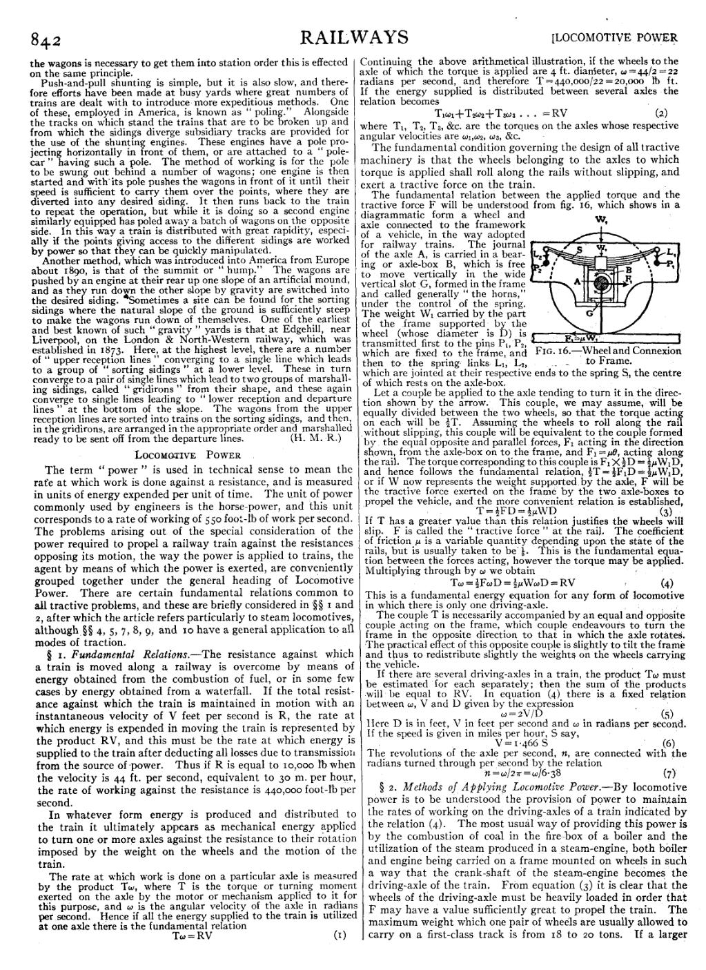
| Fig. 16.—Wheel and Connexion to Frame. |
The fundamental relation between the applied torque and the tractive force F will be understood from fig. 16, which shows in a diagrammatic form a wheel and axle connected to the framework of a vehicle, in the way adopted for railway trains. The journal of the axle A, is carried in a bearing or axle-box B, which is free to move vertically in the wide vertical slot G, formed in the frame and called generally “the horns,” under the control of the spring. The weight W₁ carried by the part of the frame supported by the wheel (whose diameter is D) is transmitted first to the pins P₁, P₂ which are fixed to the frame, and then to the spring links. L₁, L₂, which are jointed at their respective ends to the spring S, the centre of which rests on the axle-box.
Let a couple be applied to the axle tending to turn it in the direction shown by the arrow. This couple, we may assume, will be equally divided between the two wheels, so that the torque acting on each will be 12T. Assuming the wheels to roll along the rail without slipping, this couple will be equivalent to the couple formed by the equal opposite and parallel forces, F₁ acting in the direction shown, from the axle-box on to the frame, and F₁=μθ, acting along the rail. The torque corresponding to this couple is F₁ × 12D=12μW₁D, and hence follows the fundamental relation, 12T=12F₁D=12μW₁D, or if W now represents the weight supported by the axle, F will be the tractive force exerted on the frame by the two axle-boxes to propel the vehicle, and the more convenient relation is established,
| (3) |

If T has a greater value than this relation justifies the wheels will slip. F is called the “tractive force” at the rail. The coefficient of friction μ is a variable quantity depending upon the state of the rails, but is usually taken to be 15. This is the fundamental equation between the forces acting, however the torque may be applied. Multiplying through by ω we obtain
| (4) |

This is a fundamental energy equation for any form of locomotive in which there is only one driving-axle.
The couple T is necessarily accompanied by an equal and opposite couple acting on the frame, which couple endeavours to turn the frame in the opposite direction to that in which the axle rotates. The practical effect of this opposite couple is slightly to tilt the frame and thus to redistribute slightly the weights on the wheels carrying the vehicle.
If there are several driving-axles in a train, the product Tω must be estimated for each separately; then the sum of the products will be equal to RV. In equation (4) there is a fixed relation between ω, V and D given by the expression
| ω=2V/D | (5) |
Here D is in feet, V in feet per second and ω in radians per second. If the speed is given in miles per hour, S say,
| V=1·466 S | (6) |
The revolutions of the axle per second, n, are connected with the radians turned through per second by the relation
| n=ω/2π=ω/6·38 | (7) |
§ 2. Methods of Applying Locomotive Power.—By locomotive power is to be understood the provision of power to maintain the rates of working on the driving-axles of a train indicated by the relation (4). The most usual way of providing this power is by the combustion of coal in the fire-box of a boiler and the utilization of the steam produced in a steam-engine, both boiler and engine being carried on a frame mounted on wheels in such a way that the crankshaft of the steam-engine becomes the driving-axle of the train. From equation (3) it is clear that the wheels of the driving-axle must be heavily loaded in order that F may have a value sufficiently great to propel the train. The maximum weight which one pair of wheels are usually allowed to carry on a first-class track is from 18 to 20 tons. If a larger