shaft, with a hoisting engine for raising and lowering the tools.
Average rock is bored at a speed of about Iéft. per 24 hours. The
advance bore is cleaned of debris at intervals by a bailer similar to
that used for bore-holes. The enlarging trepan is so shaped that the
bottom of the enlargement slopes to the centre, whereby the cuttings,
assisted by the agitation of the water, run into the advance bore and
are bailed out. Owing to the difficulty of this latter procedure the
advance bore is sometimes omitted even for large shafts, the debris
being removed by a special dredger (Coll. Guard., Dec. 22, 1899, p.
1181). For rather loose rock another somewhat similar system of
concreting being relied on to make the lining
drilling, the Pattberg, has been satisfactorily employed.
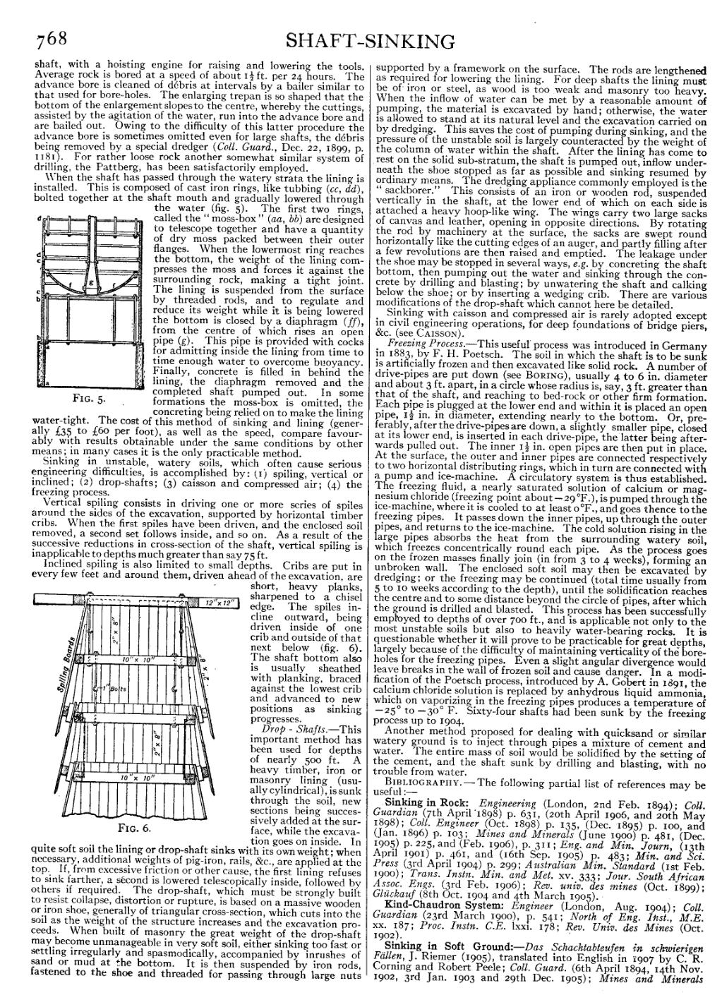
When the shaft has passed through the watery strata the lining is
installed. This is composed of cast iron rings, like tubbing (cc, dd),
bolted together at the shaft mouth and gradually lowered through
the water (fig. 5). The first two rings,
4 ~ ag 2 called the “ moss-box" (aa, bb) are designed
to telescope together and have a quantity
of dry mwofls pailkeil betweep their oulter
anges. en the owermos ring reac es
the bottom, the weight of the lining compresses the moss and forces it against the
surrounding rock, making a tight joint.
The lining is suspended from the surface by threaded rods, and to regulate and
reduce its weight while it is being lowered the bottom is closed by a diaphragm (ff), I 3 from the centre of which rises an open 2, pipe (g). This pipe is provided with cocks 2 ji for admitting inside the lining from time to A.; time enough water to overcome buoyancy. Ki Finally, concrete is filled in behind the 3 If' lining, the diaphragm removed and the completed shaft pumped out. In some
FIG- 5- formations the moss-box is omitted, the water-tight. The cost of this method of sinking and lining (generally {,35 to £60 per foot), as well as the speed, compare favourably with results obtainable under the same conditions by other means; in many cases it is the only practicable method. Sinking in unstable, watery soils, which often cause serious engineering difficulties, is accomplished by: (1) spiling, vertical or inclined; (2) drop-shafts; (3) caisson and compressed air; (4) the freezing process.
Vertical spiling consists in driving one or more series of spiles around the sides of the excavation, supported by horizontal timber cribs. /Vhen the first spiles have been driven, and the enclosed soil removed, a second set follows inside, and so on. As a result of the successive reductions in cross-section of the shaft, vertical spiling is inapplicable to depths much greater than say 75 ft. lnclined spiling is also limited to small depths. Cribs are put in every few feet and around them, driven ahead of the excavation, are I
rltlllllllllll Ill Q
lllllllll Ill
/g /gllllllllllll IK
short, heavy planks,
sharpened to a chisel
edge. The spiles incline
outward, being
driven inside of one
crib and outside of that
next below (fig. 6).
The shaft bottom also
is usually sheathed
with planking, braced
against the lowest crib
and advanced to new
positions as sinking
progresses.
Drop - Shafts.-This
important method has
been used for depths
of nearly 500 ft. A
heavy timber, iron or
masonry lining (usually
cylindrical), is sunk
through the soil, new
- - —" 12 ><12
f , / ifit
l.|| |||||i,
/lll lillllll
FIG. 6.
sections being successively
added at the surface,
while the excavation
goes on inside. In
quite soft soil the lining or drop-shaft sinks with its own weight; when necessary, additional weights of pig-iron, rails, &c., are applied at the top. If, from excessive friction or other cause, the first lining refuses to sink farther, a second is lowered telescopically inside, followed by others if required. The drop-shaft, which must be strongly built to resist collapse, distortion or rupture, is based on a massive wooden or iron shoe, generally of triangular cross-section, which cuts into the soil as the weight of the structure increases and the excavation proceeds. Vhen built of masonry the great weight of the drop-shaft may become unmanageable in very soft soil, either sinking too fast or settling irregularly and spasmodically, accompanied by inrushes of sand or mud at the bottom. It is then suspended by iron rods, fastened to the shoe and threaded for passing through large nuts supported by a framework on the surface. The rods are lengthened as required for lowering the lining. For deep shafts the lining must be of' iron or steel, as wood is too weak and masonry too heavy. When the inflow of water can be met by a reasonable amount of pumping, the material is excavated by hand; otherwise, the water is allowed to stand at its natural level and the excavation carried on by dredging. This saves the cost of pumping during sinking, and the pressure of the unstable soil is largely counteracted by the weight of the column of water within the shaft. After the lining has come to rest on the solid sub-stratum, the shaft is pumped out, inflow underneath the shoe stopped as far as possible and sinking resumed by ordinary means. The dredging appliance commonly employed is the “ sack borer." This consists of an iron or wooden rod, suspended vertically in the shaft, at the lower end of which on each side is attached a heavy hoop-like wing. The wings carry two large sacks of canvas and leather, opening in opposite directions. By rotating the rod by machinery at the surface, the sacks are swept round horizontally like the cutting edges of an auger, and partly filling after a few revolutions are then raised and emptied. The leakage under the shoe may be stopped in several ways, e.g. by concreting the shaft bottom, then pumping out the water and sinking through the concrete by drilling and blasting; by unwavering the shaft and calking below the shoe; or by inserting a wedging crib. There are various modifications of the drop-shaft which cannot here be detailed. Sinking with caisson and compressed air is rarely adopted except in civil engineering operations, for deep foundations of bridge piers, &c. (see CAISSON).
Freezing Process.-This useful' process was introduced in German in 1883, by F. H. Poetsch. The soil in which the shaft is to be sunk is artificially frozen and then excavated like solid rock. A number of drive-pipes are put down (see BORING), usually 4 to 6 in. diameter and about 3 ft. apart, in a circle whose radius is, say, 3 ft. greater than that of the shaft, and reaching to bed-rock or other firm formation. Each pipe is plugged at the lower end and within it is placed an open pipe, 1% in. in diameter, extending nearly to the bottom. Or, preferably, after the drive-pipes are down, a slightly smaller pipe, closed at its lower end, is inserted in each drive-pipe, the latter being afterwards pulled out. The inner 1% in. open pipes are then put in place. At the surface, the outer and inner pipes are connected respectively to two horizontal distributing rings, which in turn are connected with a pump and ice-machine. A circulatory system is thus established. The freezing fluid, a nearly saturated solution of calcium or magnesium chloride (freezing point about-29 °F.), is pumped through the ice-machine, where it is cooled to at least 0°F., and goes thence to the freezing pipes. It passes down the inner pipes, up through the outer pipes, and returns to the ice-machine. The cold solution rising in the large pipes absorbs the heat from the surrounding watery soil, which freezes concentrically round each pipe. As the process goes on the frozen masses finally join (in from 3 to 4 weeks), forming an unbroken wall. The enclosed soft soil may then be excavated by dredging; or the freezing may be continued (total time usually from 5 to IO weeks according to the depth), until the solidification reaches the centre and to some distance beyond the circle of pipes, after which the ground is drilled and blasted. This process has been successfully employed to depths of over 700 ft., and is applicable not only to the most unstable soils but also to heavily water-bearing rocks. It is questionable whether it will prove to be practicable for great depths, largely because of the difficulty of maintaining verticality of the boreholes for the freezing pipes. Even a slight angular divergence would leave breaks in the wall of frozen soil and cause danger. In a modification 0f the Poetsch process, introduced by A. Gobert in 1891, the calcium chloride solution is replaced by anhydrous liquid ammonia, which on vaporizing in the freezing pipes produces a temperature of -25° to -30° F. Sixty—four shafts had been sunk by the freezing process up to 1904.
Another method proposed for dealing with quicksand or similar watery ground is to inject through pipes a mixture of cement and water. The entire mass of soil would be solidified by the setting of the cement, and the shaft sunk by drilling and blasting, with no trouble from water.
E§ IlTl, IOGRAPIIY.*Th€ following partial list of references may be use u:-
Sinking in Rock: Engineering (London, 2nd Feb. 1894); Coll. Guardian (7th Apri1'1898) p. 631, (20th April 1906, and 20th May 1898); Colt. Engineer (Oct. 1898) p. 135, (Dec. 1895) p. 100, and (Jan. 1896) p. 103; Mines and Minerals (June 1900) p. 481, (Dec. 1905) p. 225, and (Feb. 1906), p. 311; Eng. and Min. Journ, (13th April 1901) p. 461, and (16th Sep. 1905) p. 483; Min. and Sei. Press (3rd April 1904) p. 299; Australian Min. Standard (1st Feb. 1900); T rans. Instn. Min. and Illet. xv. 333; Jour. South African Assoc. Engs. (3rd Feb. 1906); Rev. nniv. des rnines (Oct. 1899); Gtitekauf (8th Oct. 1904 and 4th March 1905). » Kind-Chaudron System: Engineer (London, Aug. 1904); Coll. Guardian (23rd March 1900), p. 541; North of Eng. Inst., M.E. xx. 387; Proc. Instn. C.E. lxxi. 178; Rev. Univ. des Mines (Oct. 1902 .
Sinking in Soft Ground:-Das Schaehtabteufen in sclrwierigen Fdllen, ]. Riemer (1905), translated into English in 1907 by C. R. Corning and Robert Peele; Coll. Guard. (6th April 1894, 14th Nov. 1902, 3rd Jan. 1903 and 29th Dec. 1905); Mines and Minerals