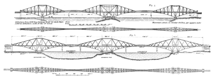
manent way on the bridge, and conduct and manage all traffic, while the Forth Bridge Railway Company undertakes to keep the structure generally in repair and good order.
THE FORTH BRIDGE, CANTILEVER TYPE; ORIGINAL AND FINAL DESIGNS
MESSRS. HARRISON, BARLOW, FOWLER, AND BAKER, ENGINEERS.
On Cantilever Bridges Generally
Some little confusion of thought would appear to exist in many minds as regards this type of construction. Most people are willing to concede the antiquity of the arch and of the suspension system, but are doubtful whether the "continuous girder," if it be rechristened "cantilever and central girder," be not a modern and patentable invention. As a matter of fact, it is a pre-historic arrangement. In the earliest Egyptian and Indian temples will be found the stone corbel and lintel combination shown in Fig. 6 (see next page), and in the oldest, as in the most modern, wooden bridges will be seen practically the same thing in timber (Fig. 7).
Skeleton bridges on a similar principle have for ages past been thrown by savages across rivers. A sketch of one such on the route of the Canadian Pacific Railway is given in Fig. 8. Perhaps one of the most interesting structures of this kind ever built is a bridge in Thibet, constructed about 220 years ago, and illustrated by Fig. 9.
This sketch is reproduced from a drawing made in 1783 by Lieutenant Davis, R.N., who formed part of the embassy to the Court of the Teshoo Lama in Thibet, an account of which with illustrations was published in London in the year 1800. The book was a popular one at the time, and was translated and republished in Germany, so that both English and German engineers had the opportunity eighty years ago of reading the following, probably the first, description of a "cantilever and central girder" bridge ever published. "The bridge of Wandipore is of singular lightness and beauty in its appearance. The span measures 112 ft.; it consists of three parts, two sides, and a centre nearly equal to each other, the sides having a considerable slope raise the elevation of the centre platform, which is horizontal, some feet above the floor of the galleries. A quadruple row of timbers, their ends being set in the masonry of the bank, and the pier supports the sides; the centre part is laid from side to side." Making allowance for difference of material the preceding work may fairly be looked upon as the prototype of the proposed Forth Bridge.
Descending to more recent times, it will be found that the term "cantilever and central girder" has ever been familiar as a household word to all educated engineers, because in treating on the strains in continuous girders it has almost invariably been the rule of authors to regard the structure as a central girder suspended from two cantilevers at the points of contrary flexure. Thus writing in 1850 on the Britannia Bridge, Mr. Edwin Clark premises severing the beam at the point of contrary flexure, and suspending the central portion from the "semi-beams or cantilevers," and appends the diagram (Fig. 10) in illustration of the resultant strains.
He also gives a sketch (Fig. 11) of "a shorter tube resting on brackets from the pier at either extremity, as below," which had been discussed by Mr. Stephenson in 1846.
In the former year also Sir John Fowler not only talked about severing the beam at the point of contrary flexure and suspending it, but had the experiment tried with a large wooden model, and the result was recorded in the discussion on the Torksey Bridge (Min. Proc. Inst. C.E., vol. ix., page 256).
In 1855 Mr. Barton, in a paper on the Boyne Viaduct (Min. Proc. Inst. C.E., vol. xiv., page 457), pointed out that the points of contrary flexure might be made to coincide with any previously determined points by severing the beam, and he added this most suggestive comment: "In very large spans where it may be a matter of great importance to reduce the weight in the middle of the beam as much as possible, the quantity in material in the top and bottom tables, as well as of the sides, may be reduced to a minimum by throwing the points of contrary flexure towards the middle of the beam, the great weight of material being placed over the piers." This is exactly what has been done in the Forth Bridge girders.
In 1858, Mr. Latham, in his well-known work on wrought-iron bridges (page 222), also speaks of "a girder suspended from the cantilever girders," and in 1859 Mr. W. H. Barlow took out a patent with reference to that and other matters. He preferred making the depth at the pier 11⁄2 times the depth at the centre. In the Forth Bridge the ratio will be 7 to 1 instead of 11⁄2 to 1.
In 1862 Professor Ritter, of Hanover, in his justly popular work "Dach-und-Brucken Constructionen" (Chapter X.) again drew attention to the fact that "hinges can be employed with advantage in girder bridges;" that a "great saving of material is effected by using a continuous girder and breaking the continuity by means of hinges." To enforce his conclusions he works out in full detail the stresses upon all of the members of a continuous girder bridge of 160 metres, or, say, 525 ft. span of the type shown by Fig. 12.
In 1864 Mr. Fowler and Mr. Baker designed a steel bridge of 1000 ft. span on the said system for the proposed South Wales and Great Western Direct Railway Severn Crossing, but the span was subsequently reduced to 600 ft. An Act was obtained for the construction of the bridge, and the contract was let; but, owing to financial difficulties, the work was not proceeded with.
In 1867 Mr. Baker enforced the economical advantages of the continuous girder of varying depths in a series of articles on "Long Span

