772
��Popular Science Monthly
��pedal pin is ground as in Fig. 3 — an old broken pin will do — and is turned into the bent crank-arm. This is intended to catch into the toothed band when starting the engine. The sprocket on the right crank- arm is removed and an old bicycle sprocket put in its place after its rim has been taken off and the unnecessary spokes cut out. A hole is drilled in the end of the spoke B, Fig. 4, for the spring C. The ends of the other spokes are fitted with the pins projecting ^ in., as shown at D, Fig. 2.
The spring E is made of about No. 14- gage brass spring wire and its function is to pull the catch F against the toothed band when the starter pedal is pushed for- ward. It will take some experimenting to obtain the right adjustment for this spring so that it will perform its duty properly.
��the inside edge comes to about ^ in. out- side of the opening through which the clutch extends. This ^ in. of the chain guard is then hammered back against the stop iron. The hole is thus made larger to provide space for the added circumference to the clutch when the toothed band is put on its outer surface.
The lower stop, Fig. 6, is made of metal ^ in. wide and 3^ in. thick. This is riveted to the piece at 7, Fig. 5. A stop bolt J, Fig. 6, is put on as shown to keep the starter-arm from turning past its throwing position. The band / and the guard are held firm at the lower part with a U-shaped piece of iron K, Fig. 2. This piece is bolted to the engine bracket. A spring Fig. 7 is made of No. 8-gage brass wire and is fastened on with the stop, as
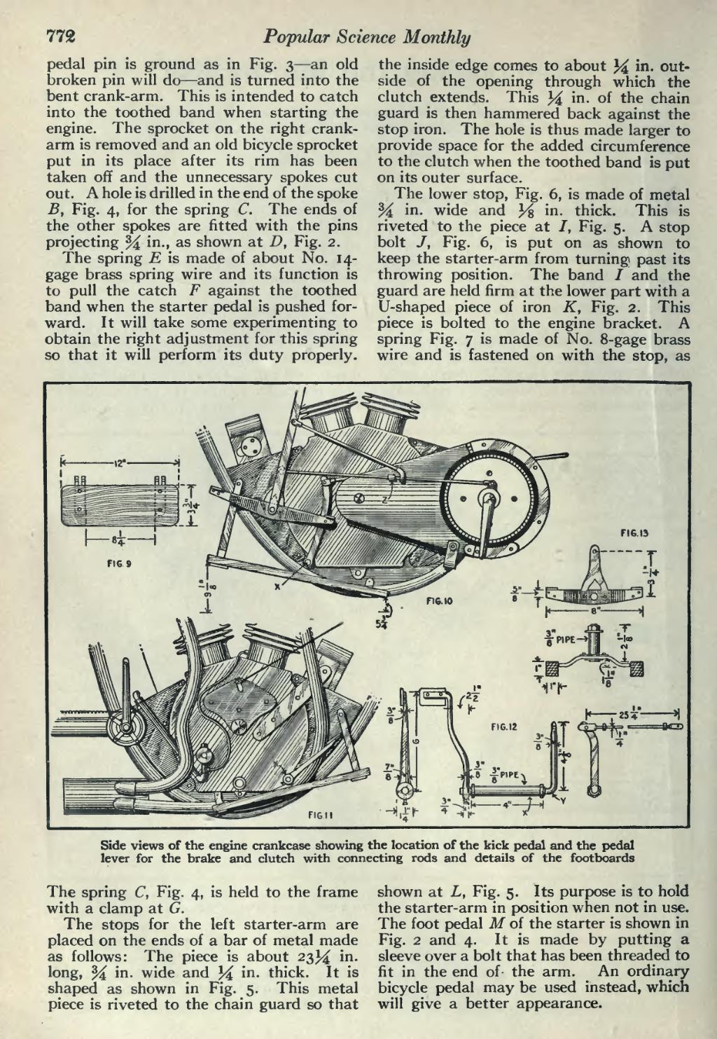
���Side views of the engine crankcase showing the location of the kick pedal and the pedal lever for the brake and clutch with connecting rods and details of the footboards
��The spring C, Fig. 4, is held to the frame with a clamp at G.
The stops for the left starter-arm are placed on the ends of a bar of metal made as follows: The piece is about 23 J^ in. long, % in. wide and 34 in. thick. It is shaped as shown in Fig. 5. This metal piece is riveted to the chain guard so that
��shown at L, Fig. 5. Its purpose is to hold the starter-arm in position when not in use. The foot pedal M of the starter is shown in Fig. 2 and 4. It is made by putting a sleeve over a bolt that has been threaded to fit in the end of- the arm. An ordinary bicycle pedal may be used instead, which will give a better appearance.
�� �