Popular Science Monthly
��959
��these machine screws are filed down, so that they can be easily put in place and will rest flush with the surface of the plates.
From a strip of soSt brass 1/16 by 5/16 in., two i-in., and two 2-in. lengths are cut. The ends of these, which should be cut squarely, should now be bent over, the short pieces once, and the long twice, to the extent of ^-in., and M-in. holes drilled in the center of each little square hill thus formed. Now 3^-in. holes should be drilled near the flat ends of the long strips, and countersunk on the sides opposite the hills.
A short brass strip should now be slipped on the short end of each rotary plate shaft, and a long strip on each long end, hills facing up as in H and /. These pieces can be slipped into the channels in the pieces of fiber as shown, and then ad- justed by moving them in and out, as well as from side to side, till the rotary plates line up well enough to be swung into position between the fixed plates. The flat headed binding-post bolts can now be inserted in the holes in the ends of the long bearing strips.
The shafts for the rotary plates should be sawed off so as to extend 3^-in. beyond the top bearings, and the metal bushings on the composition knobs drilled with the M-in. drill to a depth of ^-in., unless they already fit the shafts, as in the case of those bought by the author. Those knobs should now be placed on the shafts and adjusted to such a position that the fixed and movable plates will, when the knob bushings rest on the top bearings, be equally separated from each other, when in the full capacity position.
Now tighten the set screws in the knob bushings and adjust the upper and lower bearings little by little, until the centers of the fixed and rotary plates lie as near as possible in one straight line, without causing any of the plates to touch. When the best adjustment possible has been obtained, the nuts on the small machine screws holding the fiber blocks should be turned up tight, and the ends of the lower sets of screws sawed off flush with the nuts. In case a few plates still touch slightly in one spot or another, they can be bent a little by hand, by pressing with th^ thumb-nail. All of the plates should swing in one direction without touching. The strip bearings should not come in contact with the fiber- support bolts.
The two phonograph records should now be marked with a compass on the smooth
��side for 3^-in. circles, which can be cut from them by following the lines with a pair of tin-cutters, or, if thick records are to be cut, with a hack-saw. The edges of the small disks formed should be made smooth with sandpaper.
The center holes in these disks can now be enlarged to accommodate the knob bushings, and three 3^-in. holes can be drilled in each disk to correspond in posi- tion with the small machine screws passing through the fiber-bearing supports, and also through the ends of the top bearings. Similar holes should also be drilled ^ in. from the edges of the composition tops in line with the center and bearing-end holes.
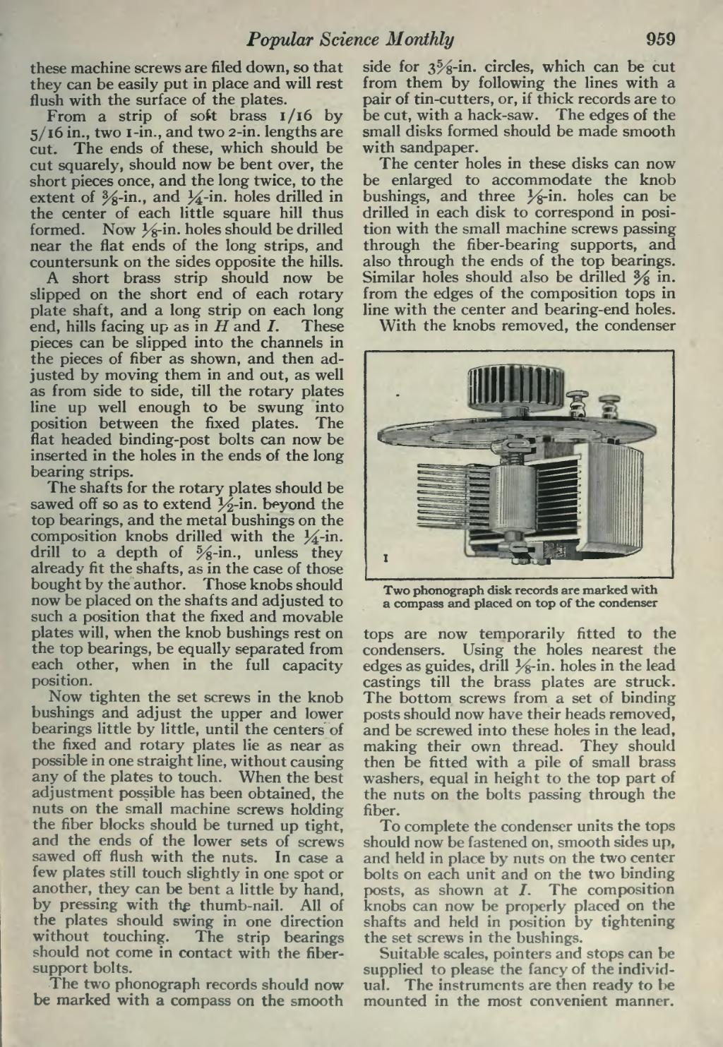
With the knobs removed, the condenser
���Two phonograph disk records are marked with a compass and placed on top of the condenser
tops are now temporarily fitted to the condensers. Using the holes nearest the edges as guides, drill 3^-in. holes in the lead castings till the brass plates are struck. The bottom screws from a set of binding posts should now have their heads removed, and be screwed into these holes in the lead, making their own thread. They should then be fitted with a pile of small brass washers, equal in height to the top part of the nuts on the bolts passing through the fiber.
To complete the condenser units the tops should now be fastened on, smooth sides up, and held in place by nuts on the two center bolts on each unit and on the two binding posts, as shown at /. The composition knobs can now be properly placed on the shafts and held in position by tightening the set screws in the bushings.
Suitable scales, pointers and stops can be supplied to please the fancy of the individ- ual. The instruments are then ready to be mounted in the most convenient manner.
�� �