310
��Popular Science Monthly
��they will establish a circuit between the line of contacts A and B. The arm contact which presses on C is connected with the handle swivel and in turn with one of the binding posts.
It can be seen that when the handle is in the neutral position, no connection is made with the motor. Moving the handle to the right or left causes the motor to ro- tate either one way or the other. This is accomplished through a reversal of the field connections. After a direction of ro- tation is established, the speed is varied by progressing the switch handle from notch to notch on contacts shown at A in the diagram. — K. M. Coggeshall.
��An Ingenious Wiring System for Two Inductive Transformers
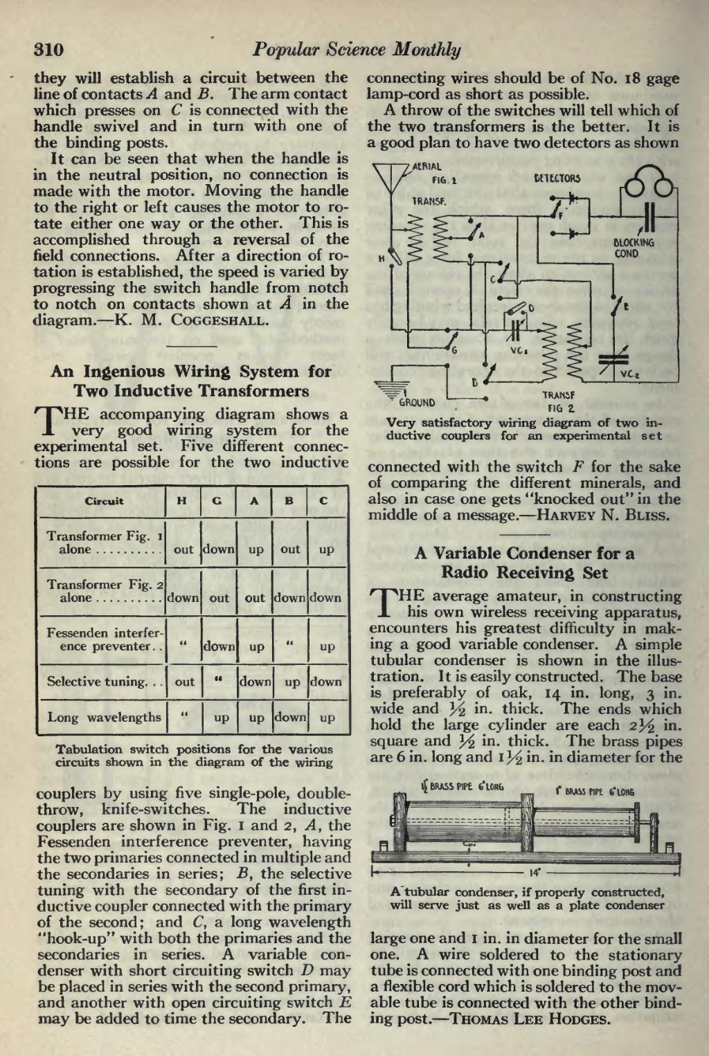
THE accompanying diagram shows a very good wiring system for the experimental set. Five different connec- tions are possible for the two inductive
��Circuit
�H
�G
�A
�B
�C
�Transformer Fig. I alone
�out
�down
�up
�out
�up
�Transformer Fig. 2
�down
�out
�out
�down
�down
� �Fessenden interfer- ence preventer. .
�<<
�down
�up
�-
�up
�Selective tuning. . .
�out
�<<
�down
�up
�down
�Long wavelengths
�»
�up
�up
�down
�up
��Tabulation switch positions circuits shown in the diagram
��for the various of the wiring
��couplers by using five single-pole, double- throw, knife-switches. The inductive couplers are shown in Fig. I and 2, A, the Fessenden interference preventer, having the two primaries connected in multiple and the secondaries in series; B, the selective tuning with the secondary of the first in- ductive coupler connected with the primary of the second; and C, a long wavelength "hook-up" with both the primaries and the secondaries in series. A variable con- denser with short circuiting switch D may be placed in series with the second primary, and another with open circuiting switch E may be added to time the secondary. The
��connecting wires should be of No. 18 gage lamp-cord as short as possible.
A throw of the switches will tell which of the two transformers is the better. It is a good plan to have two detectors as shown
���CI
��GROUND
��TRANiF FIG Z
Very satisfactory wiring diagram of two in- ductive couplers for an experimental set
connected with the switch F for the sake of comparing the different minerals, and also in case one gets "knocked out" in the middle of a message. — Harvey N. Bliss.
��A Variable Condenser for a Radio Receiving Set
THE average amateur, in constructing his own wireless receiving apparatus, encounters his greatest difficulty in mak- ing a good variable condenser. A simple tubular condenser is shown in the illus- tration. It is easily constructed. The base is preferably of oak, 14 in. long, 3 in. wide and Y2 in. thick. The ends which hold the large cylinder are each 2^ in. square and Y2 in. thick. The brass pipes are 6 in. long and 1 Y2 m - m diameter for the
��ij BRASS PIPt 6*L0Nb
��f RRASS PIPE fc'L0N6
���A" tubular condenser, if properly constructed, will serve just as well as a plate condenser
large one and 1 in. in diameter for the small one. A wire soldered to the stationary tube is connected with one binding post and a flexible cord which is soldered to the mov- able tube is connected with the other bind- ing post. — Thomas Lee Hodges.
�� �