4.48 When raised profile markings are renewed, care must be taken to ensure that the rib height is not increased above the maximum height permitted by the Regulations.
HATCHED MARKINGS
4.49 Hatched markings are prescribed as diagrams 1040, 1040.2, 1040.3, 1040.4 and 1040.5. They are also prescribed in diagrams 1013.3 and 1013.4 (see section 5 and paras 7.11 and 7.12). Two sets of dimensions are prescribed where the boundary line is broken, and are as set out in table 4-3 for diagrams 1004 and 1004.1, i.e. a 4 m mark and 2 m gap where the speed limit is 40 mph or less, and 6 m mark and 3m gap where the speed limit is more than 40mph. Regulation 12(4) exempts these diagrams from the requirement that alternative dimensions should correspond in order to maintain the shape of the marking. This allows the width of the boundary lines to be matched to those of the centre line or warning line at either end of the hatched marking. The spacing of the diagonal marks is linked to the length of the boundary lines; the closer spacing and the wider diagonal mark is used with the longer lines.
4.50 The tapers should be applied to each side of the centre line, whether it is straight or curved, at the rates specified in table 14-1. Diagrams 1040, 1040.3and 1040.4 may be preceded by the deflection arrow to diagram 1014 (see figures 4-13 and 13-6, and table 4-6). Arrows used with diagram 1040 should be positioned in the centre line and not in the opposing carriageway as with double white lines, i.e. as shown in figure 5-2 and not as in figure 5-3.
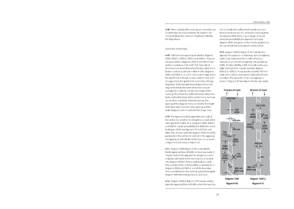
4.51 Diagram 1040 (figure 4-10) is intended to divide opposing flows of traffic on two-way roads. It may be used on the approach to refuges as a more emphatic alternative to the warning line, or to lead into diagram 1040.2. Where road studs are used, they must be white, and should be uni-directional. In diagrams 1040 and 1040.2, one of the boundary lines is omitted when the marking is placed alongside diagram 1049 delineating a bus or cycle lane.
4.52 Diagram 1040.2 (figure 4-11) may be used to separate opposing flows of traffic where the warning line is considered insufficient at hazards such as a bend or the brow of a hill. Unless this marking starts at a physical obstruction, e.g. a refuge, it should always be preceded by the tapered marking to diagram 1040. See paras 7.2 to 7.12 for guidance onthe use of hatched markings at a road junction.
4.53 Diagram 1040.3 (figure 4-12) indicates the approach to a place on a motorway, dual carriageway road or slip road where the number of lanes is reduced, or an area of carriageway not available to traffic. It is bounded by a 200 mm wide continuous edge marking which may be varied to diagram1012.2 or 1012.3. It may also be varied to 150 mm wide when used on all-purpose roads without hard shoulders. The layout for a main carriageway is shown in figure 4-13 (see figure 10-4 for slip roads).

23