side is broken, it should be replaced with a continuous line between the refuge and a point V metres in advance of it (see table 5-2). This avoids inviting an unsafe overtaking manoeuvre.
ROAD JUNCTIONS
5.19 Improved visibility sometimes results in reversion to a broken line on the approach to a junction. In such cases, it is better to maintain the continuous line beyond the junction to avoid encouraging overtaking at an unsuitable point.
5.20 The Regulations permit vehicles to cross the continuous line to enter any other road or private access (regulation 26(6)). A gap in the line is not therefore necessary. However, where there is a dedicated right turn lane this should be marked out as shown in figure 7-4 and described in para 7.11. The Directions do not require deflection arrows at the recommencement of the double line either side of the junction.
5.21 The use of double white lines in conjunction with a right turn lane on a road with a climbing lane is dealt with in para 7.12.
VISIBILITY DISTANCE
5.22 Visibility distance is defined as the maximum distance at which an object 1.05 m above the carriageway can be seen by an observer at the same height, taking account of vertical as well as horizontal curvature. In table 5-2, for each speed interval, V is the desirable minimum visibility distance and W is the warning line visibility distance as measured between points on the centre of the carriageway. Warning lines are laid where overtaking is potentially hazardous, but visibility is not so restricted that overtaking needs to be prohibited (see paras 4.12 to 4.26).
| 85 percentile speed (mph) |
Desirable minimum visibility distance V (m) |
Warning line visibility distance W (m) |
|---|---|---|
| Up to 30 | 75 | 115 |
| 31 to 40 | 95 | 160 |
| 41 to 50 | 120 | 195 |
| 51 to 60 | 150 | 240 |
| Over 60 | 175 | 275 |

DESIGN PROCEDURE FOR TWO-LANE ROADS
5.23 Double white line systems (see para 5.3) should not be designed entirely on the basis of plans and sight distance data. A site visit should always be made, and other relevant information such as the accident record taken into account. The complete scheme, with all adjustments, deflection arrows and associated markings should then be designed on a large-scale plan before any markings are laid on the road. The visibility distances used to determine the double line scheme should be based on actual 85th percentile measured speeds where this is higher than the speed limit. For measured 85th percentile speeds of 30 mph or less (see table 5-2) the visibility distances for 30 mph should be used.
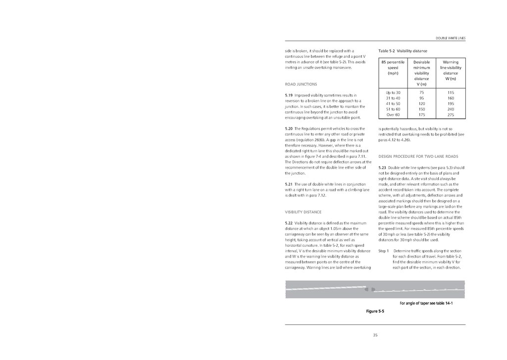
| Step 1 | Determine traffic speeds along the sectionfor each direction of travel. From table 5-2,find the desirable minimum visibility V for each part of the section, in each direction. |
35