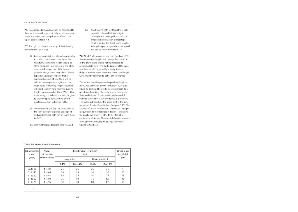
7.6 Central islands should normally be developed to their maximum width symmetrically about the centreline of the major road using diagram 1040 at the tapers set out in table 7-2.
7.7 The right turn lane is made up of the following elements (see figure 7-2):
(i)turning length (a); this allows long vehicles to position themselves correctly for the right turn. The turning length should be 10m, measured from the centre line of the minor road irrespective of the type of junction, design speed or gradient. Where capacity calculations indicate that for significant periods of time there will be vehicles queuing to turn right from the major road,the turning length should be increased to allow for a reservoir queuing length to accommodate them. Where this is necessary, consideration should be given to providing physical islands to afford greater protection to turning traffic,
(ii)deceleration length (b); this component of the right turn lane depends upon speedand gradient; its length can be found from table 7-2,
(iii)lane widths (c) and (d) (see para 7.4), and
(iv)direct taper length (e); this is the lengthover which the width (d) of a right-turning lane is developed. It should be introduced by means of a direct taper which is part of the deceleration length. Its length depends upon the traffic speed and can be found from table 7-2.
7.8 At left / right staggered junctions (see figure 7-3), the deceleration lengths will overlap, but the width of the ghost island should not be increased to accommodate them. The starting points of the right turn lane should be joined by a straight line to diagram 1004 or 1004.1 over the direct taper length(which will be common to both right turn lanes).
7.9 Where the 85th percentile speed is 40 mph or more, two deflection arrows to diagram 1014 (see figure 13-6) should be used on each approach to a ghost island marking; they may also be used where the speed is lower. A third arrow may be used if visibility is limited or if late overtaking is a problem. The spacing depends on the speed limit in the same manner as for double white lines (see para 5.15). The location of arrows in relation to the start of the taper is equivalent to the distances in table 5-1 indicating the position of arrows relative to the start of a continuous white line. The use of deflection arrows in association with double white lines is shown in figures 5-2 and 5-3.
| 85 percentile speed (mph) |
Taper either side of centre line |
Deceleration length (b) (m) |
Direct taper length (e) (m) | |||
|---|---|---|---|---|---|---|
| Up gradient | Down gradient | |||||
| 0-4% | Over 4% | 0-4% | Over 4% | |||
| Up to 30 | 1 in 40 | 25 | 25 | 25 | 5 | 25 |
| 31 to 40 | 1 in 40 | 30 | 30 | 50 | 10 | 25 |
| 41 to 50 | 1 in 45 | 50 | 50 | 75 | 15 | 35 |
| 51 to 60 | 1 in 50 | 75 | 75 | 105 | 25 | 50 |
| 61 to 70 | 1 in 55 | 100 | 100 | 135 | 30 | 70 |
46