10.10 Where the number of lanes gained is less than the number of lanes on the entry slip road, there are three methods of carrying out the merge:
(i) the two-lane slip road is reduced to one lane in advance of the back of the nose, so that the number of lanes on the entry slip road equals the number of lanes gained. The lane reduction should be effected by the use of hatched markings to diagram 1040.3 (see para 4.53 and figure 10-4). The taper length should be determined from table 10-3 and the full reduction in width achieved 50 m in advance of the back of the nose. The hatching should then be extended to the end of the slip road to form part of the nose. Additionally, at least two deflection arrows to diagram 1014 should be placed in the lane which is to be discontinued. The tip of the final arrow should be 30 m before the start of the taper and preceding arrows at intervals of 30 m in advance of that. The markings should be supplemented by signs to diagram 872.1,
(ii) the right hand slip lane merges with the through carriageway before the left hand slip lane is added (figure 10-5). All lane markings to diagrams 1005 or 1005.1 should change to 1004 or 1004.1 respectively (see table 10-4), commencing at the first sign to diagram 874 on the slip road and at least 200 m prior to the merge nose tip on the main carriageway. These markings should be continued for at least 50 m beyond the termination of the ghost island. Road markings to diagram 1010 should extend from the tip of the merge nose to the point where it meets the ghost island. Ahead arrows to diagram 1038 should be placed on the joining (additional) lane and on the original left lane of the main carriageway at the point they come together, to discourage premature lane changing,
(iii) the left hand slip lane merges with the additional main carriageway lane after the right hand slip lane has been added to the through carriageway (figure 10-6). In this option it is not easy for slower slip road traffic to merge into the faster lanes; it is also difficult to sign. Reference should be made to the appropriate overseeing authority before it is used.
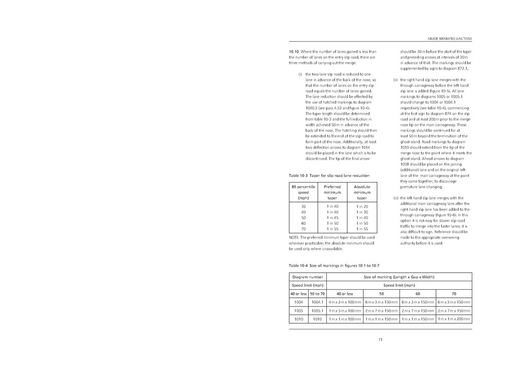
| 85 percentile speed (mph) |
Preferred minimum taper |
Absolute minimum taper |
|---|---|---|
| 30 | 1 in 40 | 1 in 20 |
| 40 | 1 in 40 | 1 in 30 |
| 50 | 1 in 45 | 1 in 40 |
| 60 | 1 in 50 | 1 in 50 |
| 70 | 1 in 55 | 1 in 55 |
NOTE: The preferred minimum taper should be used wherever practicable; the absolute minimum should be used only where unavoidable.
| Diagram number | Size of marking (Length x Gap x Width) | ||||
|---|---|---|---|---|---|
| Speed limit (mph) | Speed limit (mph) | ||||
| 40 or less | 50 to 70 | 40 or less | 50 | 60 | 70 |
| 1004 | 1004.1 | 4 m x 2 m x 100 mm | 6 m x 3 m x 150 mm | 6 m x 3 m x 150 mm | 6 m x 3 m x 150 mm |
| 1005 | 1005.1 | 1 m x 5 m x 100 mm | 2 m x 7 m x 150 mm | 2 m x 7 m x 150 mm | 2 m x 7 m x 150 mm |
| 1010 | 1010 | 1 m x 1 m x 100 mm | 1 m x 1 m x 150 mm | 1 m x 1 m x 150 mm | 1 m x 1 m x 200 mm |
71