1911 Encyclopædia Britannica/Ship
SHIP, the generic name (O. Eng. scip, Ger. Schiff, Gr. σκάφος, from the root skap, cf. “scoop”) for the invention by which man has contrived to convey himself and his goods upon water. The derivation of the word points to the fundamental conception by which, when realized, a means of flotation was obtained superior to the raft, which we may consider the earliest and most elementary form of vessel. The trunk of a tree hollowed out, whether by fire, or by such primitive tools as are fashioned and used with singular patience and dexterity by savage races, represents the first effort to obtain flotation depending on something other than the mere buoyancy of the material. The poets, with characteristic insight, have fastened upon these points. Homer’s hero Ulysses is instructed to make a raft with a raised platform upon it, and selects trees “withered of old, exceeding dry, that might float lightly for him” (Od. v. 240). Virgil, glorifying the dawn and early progress of the arts, tells us, “Rivers then first the hollowed alders felt” (Georg. i. 136, ii. 451). Alder is a heavy wood and not fit for rafts. But to make for the first time a dug-out canoe of alder, and so to secure its flotation, would be a triumph of primitive art, and thus the, poet’s expression represents a great step in the history of the invention of the ship.
Primitive efforts in this direction may be classified in the following order: (1) rafts—floating logs, or bundles of brushwood or reeds or rushes tied together; (2) dug-outs—hollowed trees; (3) canoes of bark, or of skin stretched on framework or inflated skins (balsas); (4) canoes or boats of pieces of wood stitched or fastened together with sinews or thongs or fibres of vegetable growth; (5) vessels of planks, stitched or bolted together with inserted ribs and decks or half decks; (6) vessels of which the framework is first set up, and the planking of the hull nailed on to them subsequently. All these in their primitive forms have survived, in various parts of the world, with different modifications marking progress in civilization. Climatic influences and racial peculiarities have imparted to them their specific characteristics, and, combined with the available choice of materials, have determined the particular type in use in each locality. Thus on the north-west coast of Australia is found the single log of buoyant wood, not hollowed out but pointed at the ends. Rafts of reeds are also found on the Australian coast. In New Guinea catamarans of three or more logs lashed together with rattan are the commonest vessel, and similar forms appear on the Madras coast and throughout the Asiatic islands. On the coast of Peru rafts made of a very buoyant wood are in use, some of them as much as 70 ft. long and 20 ft. broad; these are navigated with a sail, and, by an ingenious system of centre boards, let down either fore or aft between the lines of the timbers, can be made to tack. The sea-going raft is often fitted with a platform so as to protect the goods and persons carried from the wash of the sea. Upright timbers fixed upon the logs forming the raft support a kind of deck, which in turn is itself fenced in and covered over.[1] Thus the idea of a deck, and that of side planking to raise the freight above the level of the water and to save it from getting wet, are among the earliest typical expedients which have found their development in the progress of the art of shipbuilding.
I. History to the Invention of Steamships
Whether the observation of shells floating on the water, or of split reeds, or, as some have fancied, the nautilus, first suggested the idea of hollowing out the trunk of a tree, the practice ascends to a very remote antiquity in the history of man. Dugout canoes of a single tree have been found associated with objects of the Stone Age among the ancient Swiss lake dwellings; nor are specimens of the same class wanting from the bogs of Ireland and the estuaries of England and Scotland, some obtained from the depth of 25 ft. below the surface of the soil. The hollowed trunk itself may have suggested the use of the bark as a means of flotation. But, whatever may have been the origin of the bark canoe, its construction is a step onwards in the art of shipbuilding. For the lightness and pliability of the material necessitated the invention of some internal framework, so as to keep the sides apart, and to give the stiffness required both for purposes of propulsion and the carrying of its freight. Similarly, in countries where suitable timber was not to be found, the use of skins or other water-tight material, such as felt or canvas, covered with pitch, giving flotation, demanded also a framework to keep them distended and to bear the weight they had to carry. In the framework we have the rudimentary ship, with longitudinal bottom timbers, and ribs, and cross-pieces, imparting the requisite stiffness to the covering material. Bark canoes are found in Australia, but the American continent is their true home. In northern regions skin or Woven material made watertight supplies the place of bark.
The next step in the construction of vessels was the building up of canoes or boats by fastening pieces of wood together in a suitable form. Some of these canoes, and probably the earliest in type, are tied or stitched together with thongs or cords. The Madras surf boats are perhaps the most familiar example of this type, which, however, is found in the Straits of Magellan and in Central Africa (on the Victoria Nyanza), in the Malay Archipelago and in many islands of the Pacific. Some of these canoes show a great advance in the art of construction, being built up of pieces fitted together with ridges on their inner sides, through which the fastenings are passed.[2] These canoes have the advantage of elasticity, which gives them ease in a seaway, and a comparative immunity where ordinary boats would not hold together. In these cases the body of the canoe is constructed first and built to the shape intended, the ribs being inserted afterwards, and attached to the sides, and having for their main function the uniting of the deck and cross-pieces with the body of the canoe. Vessels thus stitched together, and with an inserted framework, have from a very early time been constructed in the Eastern seas far exceeding in size anything that would be called a canoe, and in some cases attaining to 200 tons burthen.
From the stitched form the next step onwards is to fasten the materials out of which the hull is built up by pegs or treenails; and of this system early types appear among the Polynesian islands and in the Nile boats described by Herodotus (ii. 96), the prototype of the modern “nuggur.” The raft of Ulysses described by Homer presents the same detail of construction. It is remarkable that some of the early types of boats belonging to the North Sea present an intermediate method, in which the planks are fastened together with pins or treenails, but are attached to the ribs by cords passing through holes in the ribs and corresponding holes bored through ledges cut on the inner side of each plank.
We thus arrive, in tracing primitive efforts in the art of ship construction, at a stage from which the transition to the practice of setting up the framework of ribs fastened to a timber 'keel laid lengthwise, and subsequently attaching the planking of the hull, was comparatively simple. The keel of the modern vessel may be said to have its prototype in the single log which was the parent of the dug-out. The side planking of the vessel, which has an earlier parentage than the ribs, may be traced to the attempt to fence in the platforms upon the sea-going rafts, and to the planks fastened on to the sides of dug-out canoes so as to give them a raised gunwale.[3] The ribs of the modern vessel are the development of the framework originally inserted after the completion of the hull of the canoe or built-up boat, but with the difference that they are now prior in the order of fabrication. In a word, the skeleton of the hull is now first built up, and the skin, &c., adjusted to it; whereas in the earlier types of wooden vessels the outside hull was first constructed, and the ribs, &c., added afterwards.[4] It is noticeable that the invention of the outrigger and weather platform, the use of which is at the present time distributed from the Andaman Islands eastward throughout the whole of the South Pacific, has never made its way into the Western seas. It is strange that Egyptian enterprise, which seems at a very early period to have penetrated eastward down the Red Sea and round the coasts of Arabia towards India, should not have brought it to the Nile, and that the Phoenicians, who, if the legend of their migration from the shores of the Persian Gulf to the coast of Canaan be accepted, would in all probability, in their maritime expeditions, have had opportunities of seeing it, did not introduce it to the Mediterranean. That they did not do so, if they saw it at all, would tend to prove that even in that remote antiquity both nations possessed the art of constructing vessels of a type superior to the outrigger canoes, both in speed and in carrying power.
The earliest representations that we have as yet of Egyptian vessels carry us back, according to the best authorities, to a period little short of 3000 years before Christ. Some of these are of considerable size, as is shown by the number of rowers, and by the cargo consisting in many cases of cattle. The earliest of all presents us with the peculiar mast of two pieces, stepped apart but joined at the top. In some the masts are shown lowered and laid along a high spar-deck. The larger vessels show on one side as many as twenty-one or twenty-two and in one case twenty-six oars, besides four or five steering. They show considerable camber, the two ends rising in a curved line which in some instances ends in a point, and in others is curved back and over at the stern and terminates in an ornamentation, very frequently of the familiar lotus pattern. At the bow the stem is sometimes seen to rise perpendicularly, forming a kind of forecastle, sometimes to curve backward and then forward again like a neck, which is often finished into a figure-head representing some bird or beast or Egyptian god. On the war galleys there is frequently shown a projecting bow with a metal head attached, but well above the water. This, though no doubt used as a ram, is not identical with the beak à fleur d’eau, which we shall meet with in Phoenician and Greek galleys. It is more on a level with the proembolion of the latter.
The impression as regards the build created by the drawings of the larger galleys is that of a long and somewhat wall-sided vessel with the stem and stern highly raised. The tendencies of the vessel to “hog,” or rise amidships, owing to the great weight fore and aft unsupported by the water, is corrected by a strong truss passing from stern to stern over crutches. The double mast of the earlier period seems in time to have given place to the single mast furnished with bars or rollers at the upper part, for the purpose apparently of raising or lowering the yard according to the amount of sail required. The sail in some of the galleys is shown with a bottom as well as a top yard. In the war galleys during action it is shown rolled up like a curtain with loops to the upper yard. The steering was effected by paddles, sometimes four or five in number, but generally one or two fastened either at the end of the stern or at the side, and above attached to an upright post in such a way as to allow the paddle to be worked by a tiller.
There are many remarkable details to be observed in the Egyptian vessels figured in Duemichen’s Fleet of an Egyptian Queen, and in Lepsius’s Denkmäler. The Egyptian ship, as represented from time to time in the period between 3000 and 1000 B.C., presents to us a ship proper as distinct from a large canoe or boat. It is the earliest ship of which we have cognizance. But there is a noticeable fact in connexion with Egypt which we gather from the tomb paintings to which we owe our knowledge of the Egyptian ship. It is evident from these records that there were at that same early period, inhabiting the littoral of the Mediterranean, nations who were possessed of sea-going vessels which visited the coasts of Egypt for plunder as well as for commerce, and that sea-fights were even then not uncommon. Occasionally the combination of these peoples for the purpose of attack assumed serious proportions, and we find the Pharaohs recording naval victories over combined Dardanians, Teucrians and Mysians, and, if we accept the explanations of Egyptologists, over Pelasgians, Daunians, Oscans and Sicilians. The Greeks, as they became familiar with the sea, followed in the same track. The legend of Helen in Egypt, as well as the numerous references in the Odyssey, point not only to the attraction that Egypt had for the maritime peoples, but also to long-established habits of navigation and the possession of an art of shipbuilding equal to the construction of sea-going craft capable of carrying a large number of men and a considerable cargo besides.
But the development of the ship and of the art of navigation clearly belongs to the Phoenicians. It is tantalizing to find that the earliest and almost the only evidence that we have of this development is to be gathered from Assyrian representations. The Assyrians were an inland people, and the navigation with which they were familiar was that of the two great rivers, Tigris and Euphrates. After the conquest of Phoenicia, they had knowledge of Phoenician naval enterprise, and accordingly we find the war galley of the Phoenicians represented on the walls of the palaces unearthed by Layard and his followers in Assyrian discovery. But the date does not carry us to an earlier period than 700 B.C. The vessel represented is a bireme war galley which is “aphract,” that is to say, has the upper tier of rowers unprotected and exposed to view. The apertures for the lower oars are of the same character as those which appear in Egyptian ships of a much earlier date, but without oars. The artist has shown the characteristic details, though somewhat conventionally. The fish-like snout of the beak, the line of the parodus or outside gangway, the wickerwork cancelli,[5] the shields ranged in order along the side of the bulwark, and the heads of a typical crew on deck (the πρωρεύς looking out in front in the forecastle, an ἐπιβάτης, two chiefs by the mast, and, aft, the κελευστής and κυβερνήτης. The supporting timbers of the deck are just indicated. The mast and yard and fore and back stays, with the double steering paddle, complete the picture.
But, although there can be little doubt that the Phoenicians, after the Egyptians, led the way in the development of the shipwright’s art, yet the information that we can gather concerning them is so meagre that we must go to other sources for the description of the ancient ship. The Phoenicians at an early date constructed merchant vessels capable of carrying large cargoes, and of traversing the length and breadth of the Mediterranean, perhaps even of trading to the far Cassiterides and of circumnavigating Africa. They in all probability (if not the Egyptians) invented the bireme and trireme, solving the problem by which increased oar-power and consequently speed could be obtained without any great increase in the length of the vessel.
It is, however, to the Greeks that we must turn for any detailed account of these inventions. The Homeric vessels were aphract and not even decked throughout their entire length. They carried crews averaging from fifty to a hundred and twenty men, who, we are expressly told by Thucydides, all took part in the labour of rowing, except perhaps the chiefs. The galleys do not appear to have been armed as yet with. the beak, though later poets attribute this feature to the Homeric vessel, But they had great poles used in fighting, and the term employed to describe these (ναύμαχα) implies a knowledge of naval warfare. The general characteristics are indicated by the epithets in use throughout the Iliad and the Odyssey. The Homeric ship is sharp (θοή) and swift (ὠκεῖα); it is hollow (κοίλη, γλαφυρή, μεγακήτης), black, vermilion-cheeked (μιλτοπάρῃος), dark-prowed (κυανόρῳρος), curved (κορωνίς, ἀμφφιέλισσα), well-timbered (ἐὖσσλμος), with many thwarts (πονύζυγος, ἑκατόζυγος). The stems and sterns are high, upraised, and resemble the horns of oxen (ὀρθοκραίραι). They present in the history of the shipping of the Mediterranean a type parallel with that of the Vikings’ vessels of the North Sea.
On the vases, the earliest of which may date between 700 and 600 B.C., we find the bireme with the bows finished off into a beak shaped as the head of some sea monster, and an elevated forecastle with a bulwark evidently as a means of defence. The craft portrayed in some instances are evidently pirate vessels, and exhibit a striking contrast to the trader, the broad ship of burden (φορτὶς εὐρεῖα), which they are overhauling. The trireme, which was developed from the bireme and became the Greek ship of war (the long ship, ναῦς μακρά, navis longa, par excellence), dates, so far as Greek use is concerned, from about 700 B.C. according to Thucydides, having been first built at Corinth. The earliest sea-fight that the same author knew of he places at a somewhat later date—664 B.C., more than ten centuries later than some of those portrayed in the Egyptian tomb paintings.
The trireme was the war ship of Athens during her prime, and, though succeeded and in a measure superseded by the larger rates,—quadrireme, quinquereme, and so on, up to vessels of sixteen banks of oars (inhabilis prope magnitudinis),—yet, as containing in itself the principle of which the larger rates merely exhibited an expansion, a difference in degree and not in kind, has, ever since the revival of letters, concentrated upon itself the attention of the learned who were interested in such matters. The literature connected with the question of ancient ships, if collected, would fill a small library, and the greater part of it turns upon the construction of the trireme and the disposition of the rowers therein.
During the 10th century a fresh light was thrown upon the subject by the discovery (1834) at the Peiraeus of some records of the Athenian dockyard superintendents, belonging to several years between 373–324 B.C. These were published and admirably elucidated by Boeckh. Further researches were carried out by his pupil Dr Graser. Since the publication of Graser's notable work, De re navali veterum, the subject has been copiously treated by A. Cartauld, Breusing, C. Torr and others. The references to ancient writers, and the illustrations from vases, coins, &c., have been multiplied, and, though the vexed question of the seating of the rowers cannot be regarded as settled, yet, notwithstanding some objections raised, it seems probable that something like Graser’s solution, with modifications, will eventually hold the field, especially as practical experiment has shown the possibility of a set of men, seated very nearly according to his system, using their oars with effect, and without any interference of one bank with another.
On one point it is necessary to insist, because upon it depends the right understanding of the problem. The ancients did not employ more than one man to an oar. The method employed on medieval galleys was alien to the ancient system. A. Jal, Admiral Fincati, Admiral Jurien de la Gravière and a host of other writers on the subject, some as recently as 1906, have been led to advocate erroneous, if ingenious, solutions of the problem, by neglect of, and in contradiction to, the testimony of ancient texts and representations, which overwhelmingly establish as an axiom of the ancient marine the principle of “one oar, one man.”
The distinction between “aphract” and “cataphract” vessels must not be overlooked in a description of the ancient vessels. The words, meaning “unfenced” and “fenced,” refer to the bulwarks which covered the upper tier of rowers from attack. In the aphract vessels these side plankings were absent and the upper tier of rowers was exposed to view from the side. Both classes of vessels had upper and lower decks, but the aphract class carried their decks on a lower level than the cataphract. The system of side planking with a view to the protection of the rowers dates from a very early period, as may be seen in some of the Egyptian representations, but among the Greeks it does not seem to have been adopted till long after the Homeric period. The Thasians are credited with the introduction of the improvement.
In our account of the trireme, both as regards the disposition of the rowers and the construction of the vessel, we have mainly, though not entirely, followed Graser. Any such scheme must at the best be hypothetical, based upon inference from the ancient texts, or upon necessities of construction, and in every case plenty of room will be left for the critic, along with the Horatian invitation, “si quid novisti rectius istis, Candidus imperti.”
In the ancient vessels the object of arranging the oars in banks was to economize horizontal space, and to obtain an increase in the number of oars without having to lengthen the vessel. It has been reasonably inferred from a passage in Vitruvius[6] that the “interscalmium,” or space horizontally measured from oar to oar, was 2 cubits. This is exactly borne out by the proportions of an Attic aphract trireme, as shown on a fragment of a bas-relief found in the Acropolis. The rowers in all classes of banked vessels sat in the same vertical plane, and seats ascending in a line obliquely towards the stern of the vessel. Thus in a trireme the thranite, or oarsman of the highest bank, was nearest the stern of the set of three to which he belonged. Next behind him and somewhat below him sat his zygite, or oarsman of the second bank; and next below and behind the zygite sat the thalamite, or oarsman of the lowest bank. The vertical distance between these seats was probably 2 ft., the horizontal distance about 1 ft. The horizontal distance, it is-well to repeat, between each seat in the same bank was 3 ft. (the seat itself about 9 in. broad). Each man had a resting place for his feet, somewhat wide apart, fixed to the bench of the man on the row next below and in front of him. In rowing, the upper hand, as is shown in most of the representations which remain, was held with the palm turned inwards towards the body. This is accounted for by the angle at which the oar was worked. The lowest rank used the shortest oars, and the difference of the length of the oars on board was caused by the curvature of the ship’s side. Thus, looked at from within, the rowers amidship seemed to be using the longest oars, but outside the vessel, as we are expressly told, all the oar-blades of the same bank took the water in the same longitudinal line. The lowest or thalamite oarports were 3 ft., the zygite 414 ft., the thranite 512 ft. above the water. Each oar-port was protected by an ascoma or leather bag, which fitted over the oar, closing the aperture against the wash of the sea without impeding the action of the oar. The oar was attached by a thong (τροπός, τροπωτήρ) to a thowl (οκαλμός). The port-hole was probably oval in shape (the Egyptian and Assyrian pictures show an oblong). We know that it was large enough for a man’s head to be thrust through it.
The benches on which the rowers sat ran from the vessel’s side to timbers, which, inclined at an angle of about 64° towards the ship’s stern, reached from the lower to the upper deck. These timbers were, according to Graser, called the diaphragmata. In the trireme each diaphragm supported three, in the quinquereme five, in the octireme eight, and in the famous tesseraconteres forty seats of rowers, who all belonged to the same “complexus,” though each to a different bank. In effect, when once the principle of construction had been established in the trireme, the increase to larger rates was effected, so far as the motive power was concerned, by lengthening the diaphragmata upwards, while the increase in the length of the vessel gave a greater number of rowers to each bank. The upper tiers of oarsmen exceeded in number those below, as the contraction of the sides of the vessel left less available space towards the bows.
Of the length of the oars in the trireme we have an indication in the fact that the length of supernumerary oars (περίνεῳ) rowed from the gangway above the thranites, and, therefore, probably slightly exceeding the thranitic oars in length, is given in the Attic tables as 14 ft. 3 in. The thranites were probably about 14 ft. The zygite, in proportion to the measurement, must have been 1012, the thalamite 712 ft. long. Comparing modern oars with these, we find that the longest oars used in the British navy are 18 ft. The university boat race has been rowed with oars 12 ft. 6 in. The proportion of the loom inboard was about one third, but the oars of) the rowers amidship must have been somewhat longer inboard. The size of the loom inboard preserved the necessary equilibrium. The long oars of the larger rates were weighted inboard with lead. Thus the topmost oars of the tesseraconteres, of which the length is given as 53 ft., were exactly balanced at the rowlock. (See Oar.)
Let us now consider the construction of the vessel itself. In the cataphract class the lower deck was 1 ft. above the water-line. Below this deck was the hold, which contained a certain amount of ballast, and through an aperture in this deck the buckets for baling were worked, entailing a labour which was constant and severe on board an ancient ship at sea. The keel (τρόπις) appears to have had considerable camber. Under it was a strong false keel (χέλυσμα), very necessary for vessels that were constantly drawn up on the shore. Above the keel was the kelson, under which the ribs were fastened. These were so arranged as to give the necessary intervals for the oar-ports above. Above the kelson lay the upper false keel, into which the mast was stepped. The stem (στεῖρα) rose from the keel at an angle of about 70° to the water. Within was an apron (φάλκης), which was a strong piece of timber curved and fitting to the end of the keel and beginning of the stern-post and firmly bolted into both, thus giving solidity to the bows, which had to bear the beak and sustain the shock of ramming. The stem was carried upwards and curved generally backwards towards the forecastle and rising above it, and then curving forwards again terminated in an ornament which was called the acrostolion. The stern-post was carried up at a similar angle to the bow, and, rising high over the poop, was curved round into an ornament which was called “aplustre” (ἄφλαστον). But, inasmuch as the steering was effected by means of two rudders (πηδάλια), one on either side, there was no need to carry out the stern into a rudder post as with modern ships, and the stern was left, therefore, much more free, an advantage in respect of the manœuvring of the ancient Greek man-of-war, the weapon being the beak or rostrum, and the power of turning quickly being of the 'highest importance.
Behind the “aplustre,” and curving backwards, was the “cheniscus” (χηνίσκος), or goose-head, symbolizing the floating powers of the vessel. After the ribs had been set up and covered in on both sides with planking, the sides of the vessel were further strengthened by waling-pieces carried from stern to stem and meeting in front of the stern-post. These were further strengthened with additional balks of timber, the lower waling-pieces meeting about the water-level and prolonged into a sharp three-toothed spur, of which the middle tooth was the longest. This was covered with hard metal (generally bronze) and formed the beak. The whole structure of the beak projected about 10 ft. beyond the stern-post. Above it, but projecting much less beyond the stern-post, was the “proembolion” (προεμβόλιον), or second beak, in which the prolongation of the upper set of waling-pieces met. This was generally fashioned into the figure of a ram’s head, also covered with metal; and sometimes again between this and the beak the second line of waling-pieces met in another metal boss called the προμβολίς. These bosses, when a vessel was rammed, completed the work of destruction begun by the sharp beak at the water-level, giving a racking blow which caused it to heel over and so eased it off the beak, and releasing the latter before the weight of the sinking vessel could come upon it. At the point where the prolongation of the second and third waling-pieces began to converge inwards towards the stem on either side of the vessel stout catheads (ἐπωτίδες) projected, which were of use, not only as supports for the anchors, but also as a means of inflicting damage on the upper part of an enemy’s vessel, while protecting the side gangways of its own and the banks of oars that worked under them. The catheads were strengthened by strong balks of timber, which were firmly bolted to them under either extremity and both within and without, and ran to the ship’s side. Above the curvature of the upper waling-pieces into the προεμβόλιον were the cheeks of the vessel, generally painted red, and in the upper part of these the eyes (ὀφθαλμοι), answering to our hawse holes, through which ran the cables for the anchors. On either side the trireme, at about the level of the thranitic benches, projected a gangway (πὀφθαλμοιάροδος) resting against the ribs of the vessel. This projection was of about 18 to 24 in., which gave a space, increased to about 3 ft. by the inward curve of the prolongation of the ribs to form supports for the deck, for a passage on either side of the vessel. This gangway was planked in along its outer side so as to afford protection to the seamen and marines, who could pass along its Whole length without impeding the rowers. Here, in action, the sailors were posted as light-armed troops, and when needed could use the long supernumerary oars (περίνεῳ) mentioned above. The ribs, prolonged upwards upon an inward curve, supported on their upper ends the cross beams (στρωτῆρες) which tied the two sides of the vessel together and carried the deck. In the cataphract class these took the place of the thwarts (ζύγα) which in the earlier vessels, at a lower level, yoked together the sides of the vessel, and formed also benches for the rowers to sit on, from which the latter had their name (ζυγῖται), having been the uppermost tier of oarsmen in the bireme; while those who sat behind and below them in the hold of the vessel were called θαλαμῖται or θαλάμακες (from θάλαμος). In the trireme the additional upper tier was named from the elevated bench (θρᾶνος) on which they were placed (θρανῖται). On the deck were stationed the marines (ἐπιβάται), fighting men in heavy armour, few in number in the Attic trireme in its palmy days, but many in the Roman quinquereme, when the ramming tactics were antiquated, and wherever, as in the great battles in the harbour at Syracuse, land tactics took the place of the maritime skill which gave victory to the ram in the open sea. The space occupied by the rowers was termed ἔγκωπον. Beyond this, fore and aft, were the παρεξειρέσιαι, or parts outside the rowers. These occupied about 12 ft. of the bows and 15 ft. in the stern. In the fore part was the forecastle, with its raised deck. In the stern the decks (ἴκρια) rose in two or three gradations, upon which was a kind of deck-house for the captain and a seat for the steerer (κυβερνήτης), who steered by means of ropes attached to the tillers fixed in the upper part of the paddles, which, in later times at least, ran over wheels (τροχιλίαι), giving him the power of changing his vessel’s course with great rapidity. Behind the deck-house rose the flagstaff, on which was hoisted the pennant, and from which probably signals were given in the case of an admiral’s ship. On either side of the deck ran a balustrade (cancelli), which was covered for protection during action with felt (cilicium, παραρρύματα τριχινά) or canvas (π. λευκά). Above was stretched a strong awning of hide (κατάβλημα), as a protection against grappling irons and missiles of all kinds. In Roman vessels towers were carried up fore and aft from which darts could be showered on the enemy’s deck; the heavy corvus or boarding bridge swung suspended by a chain near the bows; and the ponderous δελφίς hung at the ends of the yards ready to fall on a vessel that came near enough alongside. But these were later inventions and for larger ships. The Attic trireme was built light for speed and for ramming purposes.
The dimensions of some dry docks discovered at Munychium and Zea, “ship-houses” as the ancients called them, afford some indications as to limitations of length and breadth in the Attic ships that used them. The measurements indicate for these houses about 150 ft. in length and 20 ft. in breadth. We may infer, therefore, that the ships housed in them did not exceed 150 by 20 ft. But there must necessarily have been some spare room in the dock houses, on either side and at both ends. Allowing 2 ft. on either side for passage room, and 10 ft. at either end, we should have room for a vessel of about 130 ft. in length including the beak, and of about 16 ft. beam. Adopting the 2 cubit “interscalmium,” the rowing space in the trireme (31 by 3) for the upper tier would equal 93 ft. Allowing 12 ft. for bows and 15 for stern and 10 ft. for beak, we have 130 ft. as the aggregate length of the war vessel of three banks of oars. This of course is conjectural, but we submit that it is a reasonable conjecture from the evidence which we possess. There was indeed every reason for keeping the vessel as short as was compatible with the necessary requirements, and it is to be remembered that it was constantly being hauled up on shore for the night and launched again in the morning. As to the “interscalmium,” it does not appear to exceed 3 ft. even in the largest boats now used in the royal navy. In the Chinese dragon boats, which are 73 ft. long and under 5 ft. beam, and have each 54 rowers or paddlers, it does not exceed 2 ft. 6 in. An oarsman whose feet are nearly on a level with his seat, as in a modern racing eight, requires more room for the swing forward of the handle of his oar in the recovery, than a man whose feet rest on a level well below that of his seat. It is not likely that the ancient oarsman swung forward more than blue-jackets do now-a-days in a man-of-war’s cutter. All the Attic triremes appear to have been built upon the same model, and their gear was interchangeable. The Athenians had a peculiar system of girding the ships with long cables (ὑποζώματα), each trireme having two or more, which, passing through eyeholes in front of the stern-post, ran all round the vessel lengthwise immediately under the waling-pieces. They were fastened at the stern and tightened up with levers. These cables, by shrinking as soon as they were wet, tightened the whole fabric of the vessel, and in action, in all probability, relieved the hull from part of the shock of ramming, the strain of which would be sustained by the waling-pieces convergent in the beaks. These rope-girdles are not to be confused with the process of undergirding or frapping, such as is narrated of the vessel in which St Paul was being carried to Italy. The trireme appears to have had two masts. In action the Greeks did not use sails, and everything that could be lowered was stowed below. The mainmasts and larger sails were often left ashore if a conflict was expected.
The crew of the Attic trireme consisted of from 200 to 225 men in all. Of these 170 were rowers—54 on the lower bank (thalamites), 54 on the middle bank (zygites), and 62 on the upper bank (thranites),—the upper oars being more numerous because of the contraction of the space available for the lower tiers near the bow and stern. Besides the rowers were about 10 marines (ἐπιβάται) and 20 seamen. The officers were the trierarch and next to him the helmsman (κυβερνήτης), who was the navigating officer of the trireme. The rowers descended into the seven-foot space between the diaphragmata and took their places in regular order, beginning with the thalamites. The economy of space was such that, as Cicero remarks, there was not room for one man more.
The improvement made in the build of their vessels by the Corinthian and Syracusan shipwrights, by which the bows were so much strengthened that they were able to meet the Athenian attack stem on (προςβολή), caused a change of tactics, and gave an impetus to the building of larger vessels—quadriremes and quinqueremes—in which increased oar-power was available for the propulsion of the heavier weights.
In principle these vessels were only expansions of the trireme, so far as the disposition of the rowers was concerned, but the speed could not have increased in proportion to the weight, and hence arose the variety of contrivances which superseded the ramming tactics of 'the days of Phormio. In the century that succeeded the close of the Peloponnesian War the fashion of building big vessels became prevalent. We hear of various numbers of banks of oars up to sixteen (ἑκκαιδεκήρης)—the big vessel of Demetrius Poliorcetes. The famous tesseraconteres or forty-banked vessel of Ptolemy Philopator, if it ever existed except in the imagination of Callixenus, was in reality nothing more than a costly and ingenious toy, and never of any practical use. The story, however, of its construction indicates the perfection to which the shipwright’s art had been carried among the ancients.
The Romans, who developed their naval power during the First Punic War, though it is clear from the treaty with Carthage, 509 B.C., that they had had some maritime interests and adventurings before that great struggle began, were deficient in the art of naval construction. A Carthaginian quinquereme, which had drifted ashore, served them for a model, and with crews taught to row in a framework set up on dry land they manned a fleet which was launched in sixty days from the time that the trees were felled. Their first attempt was, as might have been expected, a failure. But they persevered, and the invention of the “corvus,” by means of which boarding were opposed to ramming tactics, gave them under Duilius (260 B.C.) victory at Mylae, and eventually the command of the sea. From that time onwards they continued to build ships of many banks, and seem to have maintained their predilection for fighting at close quarters. The larger vessels with their “turres,” or castles, fore and aft, deserved Horace’s description as “alta navium propugnacula.” The “corvus” and the “dolphin” were ready in action to fall on the enemy’s decks, and in Caesar’s battle with the Veneti off the coast of Gaul the “falces,” great spars with curved steel heads like a sickle, mowed through the rigging and let down the sails on which alone the foe depended for movement.
But the fashion of building big ships received a severe shock at the battle of Actium (31 B.C.), when the light Liburnian “biremes,” eluding the heavy missiles of the larger vessels, swept away their banks of oars, leaving them crippled and unable to move, till one by one they were burnt down to the water’s edge and sank.[7] After this experience the Romans adopted the Liburnians as their principal model, and though the building of vessels with many banks continued for some centuries, yet the Liburnian type was so far dominant that the name was used generically, just as the name of trireme had been used before, to signify a man-of-war, without reference to the size of vessel or the number of banks of oars.
Meanwhile, with the peace of the Mediterranean ensured, for piracy was kept in abeyance by the imperial power, and with increased commercial activity, the building of large merchant vessels naturally followed. These were propelled by sails and not by oars, which, however, continued to furnish the principal motive power for the ship of war until the necessity for increasing its carrying power began to make it too unwieldy for propulsion by rowing.
The great corn ships, which brought supplies from Egypt to the capital, were, if we may take the vessel described by Lucian as a typical instance, 120 cubits long by 30 broad and 29 deep. The ship in which St Paul and his companions were wrecked carried 276 souls besides cargo. Even larger vessels than these were constructed by the Romans for the transport of marbles and great obelisks to Italy. These huge vessels carried three masts, with square sails, and on the main mast a topsail, which the corn ships from Alexandria alone were allowed to keep set when coming into the Italian port. All other merchant vessels were compelled to strike the supparum.
But while the construction of large, vessels for commercial purposes was thus developed, the policy of keeping the war-vessel light and handy for manœuvring purposes prevailed, and, though vessels of three, four or even five banks were still built, the great majority did not rise above two banks. In the war with the Vandals (A.D. 440–470) we hear of ships of a single bank, with decks above the rowers. These, we are told, were of the type which at a later date were called Dromons (δρόμωνες) in allusion to their speedy qualities, a name which gradually superseded the Liburnian, as indicating a man-of-war. During the following centuries the Mediterranean was the scene of constant naval activity. The rise of the Mussulman power, which by A.D. 825 had mastered Crete and Sicily, made the maintenance of their fleet a matter of first importance to the emperors of the East, and as the Arab inroads became more threatening, and piracy more rife, so the necessity of improving their galleys as regards speed and armament became more and more pressing. It was during this period, and that very largely by the Arabs, that a great advance was made in the employment of what we should call artillery. The use of Greek fire and of other detonating and combustible mixtures, launched by siphons or in the form of bombs thrown by hand or machinery, led to various devices by way of protective armour, such as leather or felt casing, or woollen stuffs soaked in vinegar, and all such contrivances tended gradually to alter the character as well as the equipment of the war vessel.
During the same period the rise and growth of the Venetian republic mark the entrance on the scene of a new seafaring and shipbuilding power.
Meanwhile, the northern seas were breeding a new terror. In the 5th century the Roman fleet which guarded the narrow entrance into the British Channel had disappeared. The Frankish power gradually established itself in Gaul. But behind the Franks still fiercer races, born to the use of oar and sail, were gathering for the invasion of the west and south. For a while it seemed as if the empire consolidated by Charlemagne would be able to withstand their inroads. Yet even in the year of his Coronation (A.D. 800) the piratical Northmen had carried their ravages as far as Aquitaine. Charlemagne organized a naval force at Boulogne and at Ghent. But, though in alliance with the kings of Mercia and Wessex, he had not that control of the Channel which the possession of both shores had given to the Romans. The ships of the Vikings, propelled by oar and sail, were seagoing vessels of an excellent type. They were of various sizes, ranging from the skuta of about 30 oars to ask or skeid with 64 oars and a crew of 240, and to the still larger dreki or dragon boats, and the famous snekkjur or serpents, said to be represented on the Bayeux tapestry. Of these vessels we have fortunately, though of the smaller class, a typical instance in the well-known Viking ship discovered in 1880 in a tomb-mound at Gokstad near Christiania, of which the dimensions are given as: length 78 ft., beam 16 ft. 7 in., depth 5 ft. 9 in., with high stem and stern; clinker-built of oak throughout, with 16 oars on either side. Of this type were the vessels large and small which had by the 9th century or even earlier found their way into the Mediterranean. Such were the fleets which continually infested the northern and western coasts of Gaul, carrying swarms of the fierce Northmen who eventually came to stay, and gave their name to the portion of Neustria which they had wrested from the Frankish king (912), If, as is probable, the Danes who invaded England used the same class of vessel, Alfred the Great must, according to the Saxon Chronicle, be credited with improvements in construction, which enabled him to defeat them at sea (897). He built, we are told, vessels twice as long as those of the Danes, swifter, steadier and higher, some of them for 60 oars, and after his own design, not following either the Danish or Frisian types.
While the northern seas were thus full of activity and conflict, there was little repose in the Mediterranean. The emperors of the West do not seem to have maintained their fleets or naval stations as they had been of old. Ravenna and Misenum were shorn of their ancient glories. But in the East things were different. There, as we have said, it was fully perceived that the maintenance of the empire depended upon sea power. The Tactica of the Emperor Leo (886–911), followed by Constantine Porphyrogenitus (911–959), give us full details as to the composition of a Byzantine fleet and its units. Dromons of two sizes and of two banks of oars are described, and, besides these, smaller Dromons of great speed are referred to as “galleys or single-banked ships.” In all these the rule was still “one oar, one man,” but the way was being prepared for improvements by which the medieval galley, still preserving a comparatively low freeboard, was enabled to equal or to surpass the many-banked vessel in speed, while it was gradually adapted to carry greater weight and more powerful means of offence.
The medieval man-of-war was essentially a one-banked vessel (μονόκροτον), but the use of longer oars or sweeps took the place of the smaller paddling oars of the ancient vessel, and altered greatly the angle at which the oars reached the water. It was the increase in the length and weight of the oar, requiring for its efficiency greater power than that of one man, which led to the employment of more than one man to an oar. With the longer oar the necessity arose of placing the weight at a greater distance from the power applying the lever. This was gained by the invention of the apostis, which was practically a framework standing out on each side of the hull and running parallel to it; a strong external timber, in which the thowls, against which the oars were rowed, were set. By this means it became possible not only to arrange the oars horizontally, in sets of three or more of different lengths (alla zenzile), instead of in banks one above the other obliquely, but still further to make an innovation, unknown to the ancients, which, while greatly increasing the length and substance of the oar, and its leverage, applied the strength of three or four men (or even up to seven with the larger galleys and galleasses) for the motive power of each blade. As time went on oars of from 30 to 50 ft. came into vogue, the inboard portion of which was about one-third of the length, and furnished with handles (manettes) attached to the loom, while the men for each oar were arranged in steps (alla scaloccio).
It must not be imagined that these developments took place all at once, or that any improvements in building, or in the method of propulsion, were generally adopted but by slow degrees. Moreover, as commerce increased and merchant vessels gained in size, the necessity of being able to defend themselves against piratical attacks became more and more cogent, a necessity which ultimately led the way to the supersession of the galley by the sailing vessel. Yet the galley for centuries, especially in the Mediterranean, maintained its place as the ship of war par excellence, even when mixed fleets of galleys and sailing vessels were not uncommon. In the Atlantic and northern seas it was less en évidence, though even with the Spanish Armada some galleys and galleasses were included in the invading fleet.
The period of the Crusades was one of great activity in shipbuilding, in which the Venetians and the Genoese were the leaders in the Mediterranean, but the enterprise of England under Richard Cœur de Lion (1189–1199) shows that in the northern seas great efforts were being made in the same direction, with the undoubted result that the English nation became more familiarized with the sea, and more eager for maritime adventure. Richard’s fleet which sailed from Dartmouth consisted of 110 vessels, and its total in the Mediterranean after reinforcement amounted to 230 vessels. Among these were Busses, or Dromons of large size, with masts and sails, ships of burden and triremes. Nor were the Saracens without great vessels, if the story of Richard’s destruction of a three-masted vessel, carrying reinforcements to Acre, on board of which there were no less than 1500 men, be true. The attack of a swarm of galleys upon the great ship as she lay becalmed reads almost like the attack of a swarm of torpedo boats upon a disabled battleship to-day.
The whole period of the Crusades was, as regards naval matters, one of mixed fleets, in which the sailing vessels were mostly merchant vessels armed for fighting purposes. The effect of the Crusades upon the seafaring races of northern Europe was that the revelation of the East and its traffic quickened their desire for adventure in that and other directions. Hence rivalries between them and the Mediterranean sea powers, and consequent improvement in sea-going vessels and in seamanship. The steering side-paddle gradually disappears, and the rudder slung at the stern becomes the usual means of directing the vessel’s course. The merchant vessels when prepared for war have fore-castles and stern-castles (compare the Roman turres) erected on them, of which the one survives in name, and the other in the quarter-deck of modern times. But a change was at hand which was destined to affect all classes, from the galley with its low freeboard to the alta propugnacula of the great sailing vessels.
The invention of gunpowder, and the consequent use of cannon on board ship, was the cause of many new departures in building and armaments. In the galleys we find guns mounted in the bows, and broadside on the upper deck, en barbette, firing over the bulwarks. Soon, however, the need of cover suggested portholes cut for the guns, just as in the ancient galleys they had been cut for the oars. The desire to carry many guns led to many alterations in build, such as the tumble-home of the sides, and the desire for speed to many improvements in rig, as well as to an increase in the number of masts and consequently larger spread of sail. About 1370–1380 French, Venetians and Spaniards are using the new artillery in action, and the policy of maintaining a navy composed of sailing vessels built for the purposes of war, and not merely of armed merchant ships impressed for the emergency, soon began to take effect.
In England Henry V. (1413) built large vessels for his fleet, “great ships, cogs, carracks, ships, barges and ballingers,” some of which were of nearly 1000 tons, but the generality from 420 to 520 tons. In the list of his fleet no galleys seem to be included. Meanwhile in the south the type of vessel called “caravel” was being developed, in which Portuguese and Spaniards dared the Atlantic and made their great discoveries. It was in a vessel of this kind that Columbus (1492) sought to reach the Indies by a western route.[8] She was but little over 230 tons when fully laden. Her forecastle overhung the stem by nearly 12 ft. Aft she had a half deck and a quarter deck. Her total length was 128 ft., her beam nearly 26 ft. She had three masts and a bowsprit. Her fore and main masts were square-rigged, but the mizzen had a lateen sail. The vessels in which Vasco da Gama first doubled the Cape of Good Hope (1497) were of the same type but larger. The ship of John Cabot (1497) in which he discovered Newfoundland must have been much smaller, as he had a crew of only eighteen men.
Among the results of these world-famous voyages and discoveries was naturally a great increase in maritime adventure.
In England during the Tudor times a great advance in shipbuilding is observable. Henry VII. with his new ships, the “Regent” and the “Sovereign,” and Henry VIII. with his “Henry Grace à Dieu,” or “Great Harry,” both came abreast of their times, but it is worthy of notice that the French then, as well as at a later period, were providing the best models for naval architecture. These big ships were armed at first with “serpentines,” and later with cannon and culverins. The representations of them show several tiers of guns, four or even five masts, and enormous structures by way of forecastles and deck-houses aft. As regards merchant vessels, the Genoese and the Venetians during the 15th and 16th centuries carried out great improvements. The “carracks” of the 16th century often reached as much as 1600 tons burden. There is a record of a Portuguese carrack captured by the English, of which the dimensions reached 165 ft. in length and 47 ft. in beam. She carried 32 pieces of brass ordnance and between 600 and 700 passengers. The Spanish Armada (1588) was composed of 132 vessels, of which the largest was about 1300 tons and 30 under 100 tons. Four galleys and four galleasses accompanied the fleet. The opposing fleet consisted of 197 vessels of which only 34 belonged to the royal navy. Of these the largest was the “Triumph” of about 1000 tons. The “Ark,” the flagship of the English admiral, was of 800 tons, carrying 55 guns. Among the armed merchant vessels employed with the fleet was the “Buonaventure,” the first English vessel that made a successful voyage to the Cape and India. The result to England of the defeat of the Spaniards was a great increase of mercantile activity. Merchants, instead of hiring Genoese or Venetian carracks, began to prefer building and owning home-built ships, and though the foreign merchant vessels appear to have been on a larger scale, yet, as sea-going craft, the English-built ships certainly held their own. We hear also during this period of many improvements in details, such as striking topmasts, the use of chain pumps, the introduction of studding, top-gallant, sprit and top sails, also of the weighing of anchors by means of the capstan, and the use of long cables. In the men-of-war the lower tier of guns, which, as in the galleys, had been carried dangerously near the water-line, began to be raised. This improvement, however, does not seem to have been adopted in the English ships till after the Restoration. Meanwhile, in the Mediterranean the galley was still in vogue, being only partially superseded by the great galleasses, six of which are recorded to have taken part in the battle of Lepanto (1571), in which the Venetians and their allies employed no less than 208 galleys with single banks and long sweeping oars. The contrast between the conditions and the character of the vessels used in this battle and those engaged in the case of the Spanish Armada is interesting and instructive as typical of the different development of naval power in the inland and the open seas.
During the 17th century the expansion of trade and the increase of mercantile enterprise were incessant. The East India Company organized its fleet of armed vessels of about 600 tons, and fought its way through Portuguese obstruction to the Indian coast. The Dutch were also competing for the trade of the East and the West, and formed similar companies with this object in view. Conflicts owing to commercial rivalry and international jealousies were inevitable. Hence in the British navy the construction of large vessels such as the “Prince Royal” and the “Sovereign of the Seas” (see Rigging), which may be considered as among the earliest types of the modern wooden man-of-war. English oak afforded the best timber for shipbuilding, and skilful naval architects, such as Phineas Pett, succeeded in constructing the kind of sea-going war vessel which eventually gave England the superiority in its struggle with other naval powers in this and the following century. This, however, was by no means easily gained. The Dutch and the French were not slack in the building of merchant vessels and men-of-war. The capture of vessels from time to time on either side served to enlarge the area of improvement and to assist in the progress of the art of construction. The French navy especially, under the fostering care of Colbert, was greatly strengthened. During the 18th century it was constantly found that the dimensions of French ships exceeded those of British ships of the same date, and that French vessels were superior in speed. This led from time to time to an increase of the measurements of the various classes of vessels in the British navy. These were now rated according to the number of guns which they were constructed to carry.
A 90-gun ship of the line at the beginning of the 18th century averaged 164 ft. in length of gun deck, 47 ft. beam, and about 1570 tons, while the frigates now ran to 120 ft. with 34 ft. beam and from 600 to 700 tons. These dimensions, however, were not always maintained, and towards the middle of the century the Admiralty seem to have recognized the consequent inferiority of their ships. The famous and ill-fated “Royal George,” launched in 1756, was the result of an effort to improve the line-of-battle ship of the period. She was 178 ft. in length, 52 ft. in beam, was of over 2000 tons, and carried 100 guns and a crew of 750 men. The “Victory,” Nelson’s flagship, was built nearly ten years later. Her dimensions were 186 ft., 52 ft., 2162 tons, and she carried 100 guns. During the same period frigates, which were cruisers carrying their armament on one deck, were built to carry 32 or 36 guns, but in this class also the French cruisers were superior in speed and of larger dimensions. The remainder of the 18th century and the beginning of the 19th witnessed a continuous rivalry in naval architecture, the French and Spanish models being constantly ahead of the British in dimensions and armament. In the American war (1812) the same disparity as regards dimensions became apparent, and the English frigates, and sloops used as cruisers, were generally outclassed, and in some instances captured, by American vessels of their own rate. This as usual led to the construction of larger vessels with greater speed, and though, after the conclusion of the long war, the activity of the royal dockyards slackened, yet the great three-deckers of the last period, before the adoption of steam power, had reached a length of over 200 ft., with more than 55 ft. beam, and over 3000 tons.
Meanwhile the mercantile navies of the world, but more especially of England, had largely increased. The East Indiaman, as the armed vessels of the East India Company were called, really performed the functions of merchant vessel, passenger ship, and man-of-war. But, where there was no monopoly, competition soon quickened the development of trading vessels. The Americans with their fast-sailing “clippers” again taught the English builders a lesson, showing that increased length in proportion to beam gave greater speed, while admitting of lighter rigging in proportion to tonnage, and of economy as regards the number of men required to work the ship. The English shipyards were for a long time unequal to the task of producing vessels capable of competing with those of their American rivals, and their trade suffered accordingly. But after the repeal of the Navigation Laws in 1850 things improved, and we find clippers from Aberdeen and from the Clyde beginning to hold their own on the long voyages to China and elsewhere.
At this epoch steam power appears in use on the scene, and the period of great wooden vessels closes with iron and steel taking their place in the construction of the hulls, while the sail gives way to the paddle and the screw.
Literature.—1. For Ancient Ships:-Duemicher, Fleet of an Egyptian Queen; Chabas, Études sur l’antiquité historique; Rawlinson, Ancient Monarchies; Scheffer, De militia navali veterum; Boeckh, Urkunden über das Seewesen des attischen Staates; B. Graser, De re navali veterum; Idem, Das Model eines athenischen Fünfreihenschiffes (Pentere) aus der Zeit Alexander des Grossen im Königlichen Museum zu Berlin; Idem, Die Gemmen des Königlichen Museums zu Berlin mit Darstellungen antiker Schiffe; Idem, Die ältesten Schiffsdarstellungen auf antiken Münzen; A. Cartauld, La Trière athénienne; Breusing, Die Nautile der Alten; Smith, Voyage and Shipwreck of St Paul; C. Torr, Ancient Ships. 2. For medieval and modern shipping:—A. Jal, Archéologie navale and Glossaire nautique; Jurien de la Gravière, Derniers Jours de la marine à rames (Paris, 1885); Fincati, Le Triremi; C. de la Ronciere, Histoire de la marine française; Marquis de Folin, Bateaux et navires; W. Laird Clowes, The Royal Navy; W. S. Lindsay, History of Merchant Shipping and Ancient Commerce; Sir G. C. V. Holmes, Ancient and Modern Ships. (E. Wa.)
II. History Since the Introduction of Steamships
Before steam was applied to the propulsion of ships, the voyage from Great Britain to America lasted for some weeks; at the beginning of the 20th century the time had been reduced to about six days, and in 1910 the fastest vessels could do it in four and a half days. Similarly, the voyage to Australia, which took about thirteen weeks, had been reduced to thirty days or less. The fastest of the sailing tea-clippers required about three months to bring the early teas from China to Great Britain; in 1910 they were brought to London by the ordinary P. & O. service in five weeks. Atlantic liners now run between England and America which maintain speeds of 25 and 26 knots over the whole course, as compared with about 12 knots before the introduction of steam. The accommodation in the modern passenger ships is palatial compared with that in the corresponding wooden sailing ships of the middle of the 19th century.
The changes from sail power to steam power for propulsion, and from wood to iron and steel for constructional purposes, proceeded together, though at first very slowly. The marine steam engine was at first a very imperfect motor, and the services upon which steamships could be used to advantage were, in consequence, much restricted. There was, moreover, a national prejudice against the substitution of iron for “the Wooden Walls of Old England.”
It is recorded that an iron boat, intended apparently for passenger service, was built and launched on the river Foss, in Yorkshire, in 1777, and shortly afterwards iron was used for the shell plating of lighters for canal service. One of these, having its shell constructed of plates five-sixteenths of an inch thick, was built Introduction of iron. near Birmingham in 1787. About the same time parts of wooden ships began to be replaced by iron, the first being beam knees. Early in the 19th century iron “diagonal riders” for providing the longitudinal strength were introduced by Sir Robert Seppings, and from this period down to the present day iron strengthenings for resisting both transverse and longitudinal strains have been generally used in wooden ships. The introduction of iron as a recognized material for ship construction is often given as dating from 1818, when the lighter “Vulcan” was built on the Monkland canal, near Glasgow.
Among the early objections were: (1) from its weight iron could not be expected to float, and was therefore unsuitable for the construction of a floating body; (2 when a ship constructed of this material grounded and was exposed to bumping on a shore, the bottom would be easily perforated; (3) the bottom could not be preserved from fouling by weeds and barnacles; and (4) the iron affected the compass, making it untrustworthy, if not useless. Gradually, however, the material made its way, and the objections to it proved to be for the most part untenable. Objection (1), although often repeated, was proved to involve a fallacy. With regard to objection (2) it was found that iron ships might ground and be subjected to a great deal of bumping and rough usage without being destroyed, and that, on the whole, they were better off in this respect than wooden ships. On more than one occasion when iron and wooden ships were stranded together by the same gale and in approximately the same circumstances, the iron ships were got off, and, apart from local injury, were found to be little the worse for the grounding, while the wooden ships were either totally wrecked, or, if got off, were strained to such an extent as to be beyond repair. The power of resistance of iron ships to the strains produced by grounding received, in 1846–1847, a remarkable confirmation in connexion with the grounding of the “Great Britain,” the first large screw steamer built of iron. This ship had been initiated by, and built under the supervision of, Mr I. K. Brunel, who had bestowed much attention upon the details of her construction. In 1846 she ran ashore in Dundrum Bay, in Ireland, and settled on two detached rocks; and although she remained aground for eleven months, including a whole winter, she was subsequently got off and repaired, and afterwards did good service. As regards (3), the fouling of the bottom, this evil, although not preventable, can be lessened materially by frequent cleaning and repainting, provided, of course, that docks are available. The fourth objection, the effect of iron on the compass, was very serious. After experimenting with the “Rainbow” at Deptford and the “Ironsides” at Liverpool, Sir G. B. Airy in 1839 read a paper on the subject before the Royal Society, and the rules which he gave for the correction of the error caused by the iron at once became the guide for future practice. Besides the above, a further objection was raised which applied only to warships, namely, the nature of the damage which would be done to an iron ship by the enemy’s shot: this also was found to be less serious, when proper appliances were supplied, than the damage done in the same circumstances to a wooden ship. Thus during the Chinese War in 1842 the “Nemesis,” an iron vessel, was able to repair her damage from shot in twenty-four hours at the scene of the fight, while some wooden ships had to go to Bombay, the nearest port at which repairs could be carried out.
Steel, as a material for shipbuilding, was introduced under modern conditions of manufacture during the years 1870–1875. It is a homogeneous metal, stronger than iron, and of a more uniform and more trustworthy character. Its quality is to a considerable extent independent of the skill of those employed in its manufacture, whereas Introduction of steel. iron is produced by a laborious and unhealthy process, and is largely dependent for its quality on the skill of the workmen. Among the advantages which experience has proved iron and steel to possess over wood for the purposes of ship construction are: (1) the structure of the ship has less weight; (2) it has greater durability; (3) the requisite general and local strengths are much more easily obtained.
The importance of the first of these advantages can scarcely be overstated. The primary object of a particular ship is to carry cargo or passengers, or both, from place to place, at a given speed (in the case of a warship, the armament, ammunition, armour, &c., constitute the weight to be carried); and since at the maximum draught at which the vessel can properly and safely proceed on her passage the total weight of vessel, cargo, &c., complete, must be a definite quantity, namely, the weight of the water displaced by the ship, it follows that the less the weight required for the structure of the ship, the greater is that available for the cargo, &c.
As to durability, in wooden ships the chief source of deterioration is dry-rot, in iron or steel ships the wasting of the surfaces, especially of such portions of the outer surfaces of the bottom plating as are frequently left bare of paint and exposed to the sea, and of the inner surfaces of the bottom in machinery spaces, &c. If dry-rot can be prevented, the life of the wooden ship will be lengthened; so also will the life of the iron or steel ship if the surfaces can be kept covered with paint, to prevent the corrosive action of air and water. With both wood and iron or steel ships, if the parts which have become deteriorated can be removed and replaced, this is usually worth doing when the deterioration is only local. At the end of the 18th century the preservation of wood was not so well understood as it is at the present day, and teak, one of the most durable of woods, was, in Great Britain at least, little known. The ships for the Royal Navy as then constructed were only expected to be available for service some fifteen or twenty years. The ships built for the East India Company made, on an average, four voyages, which occupied eight years. This at one time was considered the vessel’s life, so far as the Company’s service was concerned; but subsequently, if on examination at the expiration of that time they appeared worth repairing, this was done, and they were allowed to make two more voyages. It was unusual for one of these ships to make more than six voyages; after this they were sold or broken up.
In certain cases, however, ships lasted a considerable length of time; a number of vessels built in the 17th century continued in the service of the Royal Navy until the middle of the 18th century, though with a reduced number of guns, and specimens of the old wooden battleships which served in the fleet in the earlier part of the last century are still to be found in the naval and other ports as training vessels, hospital ships, &c. The best-known example is Nelson’s “Victory” (fig. 1, Plate XIII.). Laid down in 1759, she had been afloat 40 years before she took part in the battle of Trafalgar, and to-day flies the flag of the commander-in-chief at Portsmouth. Of small wooden merchant vessels there are instances of the attainment of very remarkable ages. Lloyd’s Register for 1909–1910 shows one sailing vessel, the “Olivia” of 94 tons, as having been built as early as in 1819, two vessels built in the ’twenties, and twelve built between 1830 and 1840. The collier brig “Brotherly Love,” of South Shields, was over one hundred years old when she was broken up; and the schooner “Polly” built in 1805, was still sailing in 1902; as also was the brig “Hvalfisken,” built at Calmar in Sweden in 1801. The dimensions of the last vessel are; length, 88 ft. 8 in.; breadth, 21 ft. 2 in.; depth of hold, 14 ft. 7 in.; and her gross tonnage, 211. The oldest vessel afloat in 1910 was said to be the Danish sloop “Constance”—a small wooden sailing vessel built in 1723 and still employed in the coasting trade of Denmark. This vessel is 52 ft. 6 in. long, 14 ft. 8 in. beam, 6 ft. 8 in. depth in hold and of 35 tons gross.
In the cases of these very old wooden vessels it should be remembered that many portions of the original structures have been replaced by continual repairs. We have less experience concerning the life of iron and steel ships when taken care of, and in most instances ships have been condemned and broken up only because they were obsolete; but after twenty or even forty years’ service, those parts which by accident or intention had remained properly covered and protected were found very little the worse for wear. Thus the inner surface of the outside plating of such vessels, coated with cement, have been found to be in as good condition as when the ships were first built. The hulls of many of the early iron vessels still afloat are known to be in excellent condition. The “Himalaya,” an iron vessel of 3453 tons and 700 h.p., 6 guns, length 340 ft. 5 in., breadth 46 ft. 2 in., depth 24 ft., built by Mare of Blackwall in 1853 for the P. & O. Steam Packet Co., and purchased by the Admiralty, was actively employed, chiefly as a troop-ship, until 1896, when she was converted into a coal depot, it being found that her plating and framing were almost as good as new. Known as “C. 60,” she seemed likely in 1910 to survive for many years in her new service. The “Warrior”—the first British iron battleship, built in 1861, was converted into a floating workshop forty years later at Portsmouth, where in 1910 she was known as “Vernon III.” The hull and framing of the vessel were then practically as sound as when first put together. Experience up to 1910 with vessels built of mild steel indicates that this is more liable to surface corrosion than iron, especially where exposed to the action of bilge water and coal ashes in boiler rooms. Some owners on this account require the plating for the tank tops under the boilers to be of iron in vessels otherwise built of mild steel, although the iron is inferior in strength and costs more than the mild steel.
That general and local strength are more easily obtained in an iron or steel ship than in a wooden one follows partly from the fact that the weight required for the structure is less in the former than in the latter, and also from the fact that iron and steel are more suitable materials for the purpose. They can be obtained in almost any desired shape, the parts can be readily united to one another with comparatively little loss of strength, and great local strength can be provided in very little space.
For some purposes, and in some markets, wood is still in favour. In scientific expeditions to the Polar regions, it is of the highest importance to avoid any disturbance of the compass, and this can be ensured by constructing the vessel of wood, with metal fastenings. The “Fram,” built in 1892 for Nansen’s Arctic expedition, was of wood, her outside planking, in three thicknesses, amounting in the aggregate to from 24 in. up to 28 in.; she was 117 ft. long, rigged as a three-masted schooner, and provided with auxiliary machinery working a screw propeller. The “America,” fitted out for the Ziegler expedition to the North Pole, was an old Dundee whaler (the “Esquimaux”), and was reported to be still a “stout” ship with timbers as sound as on the day they were put in thirty-six years before. She is 157 ft. long, 2912 ft. beam, 1912 ft. deep, net tonnage 466; her engines have a nominal horse-power of 100, and she has a lifting screw. In 1901 the “Discovery,” a wooden vessel, 172 ft. in length, was built at Dundee for Antarctic exploration, under Captain Robert Scott, R.N.,[9] and a wooden vessel for similar service was constructed in Germany, and in 1910 the “Terra Nova” (Plate I., fig. 2), a wooden Dundee whaler, 187 ft. long, barque-rigged and fitted with auxiliary steam power, which had already seen service in the Far South, carried to the Antarctic regions an expedition also led by Captain Scott. Some wooden sailing vessels are still built in the United States and employed in the coasting and other trades. One of these, the “Wyoming,” the largest wooden sailing vessel ever built, was launched in December 1909 at Bath. She was a six-masted schooner 350 ft. long, 50 ft. wide and 30 ft. deep. Wood is also in favour or most of the large and palatial river steamers of the Western states of America.
Some progress had been made in the introduction of steam propulsion before the end of the 18th century, but the advance became more rapid in the 19th. In the early steam vessels paddle-wheels only were used for propulsion.Steam propulsion.
In 1801–1802 the “Charlotte Dundas,” one of the earliest steam vessels, was constructed by Symington in Scotland. She proved her capability for towing purposes on the Forth and Clyde canal. Fulton now made his experiments in France, and after visiting Scotland and witnessing the success of the “Charlotte Dundas,” constructed the “Clermont” on the Hudson river in America. in 1807. The engines for this vessel were obtained from Boulton & Watt, of England. She ran as a passenger boat between New York and Albany, and at the end of her second season proved too small for the crowd that thronged to take passage in her. In 1809 the “Phoenix” made the passage from Hoboken, in New Jersey, to Philadelphia, and was thus the first steamer to make a sea voyage. In 1812 Bell began running his steamer “Comet,” with passengers, between Glasgow, Greenock and Helensburgh: she was 42 ft. long, 11 ft. broad, 512 ft. deep, and her engine had one cylinder 11 in. in diameter, with a 16-in. stroke. Owing to the success achieved by these and other vessels in America and Great Britain, Steamers soon began to make their appearance on many of the principal rivers of the world. Early in 1814 there were five steamboats on the Thames, and the steamboat “Margery,” built on the Clyde, was brought through the Forth and Clyde canal and round by the east coast to the Thames. In the same year a writer in the Gentleman’s Magazine was able to say: “Most of the principal rivers in North America are navigated by steamboats; one of them passes 2000 m. on the great river Mississippi in twenty-one days, at the rate of 5 m. an hour against the descending current.” In 1816 the first steam passenger-boat ran across the English Channel from Brighton to Havre, and a line of steamers was started to run between New York and New London. All of these vessels were built of wood; but in 1820 the first iron steamship, the “Aaron Manby,” was constructed and employed in a direct service between London and Paris. In 1822 a return was made to the House of Commons showing the times occupied by Steamers as compared with sailing vessels on some thirty coasting routes; the average speed given for steamers in the best of these was from eight to nine knots, while the average time taken varied from one-half to one-sixth (or even less) of the time taken by the sailing vessels.
Steam vessels were employed at a very early date upon the mail services, for besides being very much quicker than the sailing vessels, they were practically independent of the direction of the wind, and to a considerable extent of the weather; consequently the regularity of their passages contrasted very favourably with the irregular times kept by the sailing vessels. The mail service across the Irish Channel, between Holyhead and Dublin, was especially uncertain in the days of the sailing packets, frequently occupying three or four days, and occasionally as much as seven and nine days. All this was altered when in 1821 the steamers “Royal Sovereign” and “Meteor” were placed on the service. The advantages were so apparent that steam mail packets between Great Britain and the Continent, and on many other services, were soon established. The mail boats had been for many years owned by the crown, but in 1833 the carrying of the mails to and from the Isle of Man, and between England and Holland and Hamburg, was entrusted to private companies. Marked improvement in the services, and especially in the boats employed, resulted from the competition to secure the distinction and other advantages of carrying His Majesty’s mails. An intermediate stage followed, extending over a comparatively short period, during which the crown still held many of the mail boats, while in a considerable number of cases the mail services were let to private companies. After this the British government abandoned altogether the policy of being the owners of the boats, and the mail services have since been competed for by private companies.
The “Savannah” was the first steamship to cross the Atlantic. She ran from Savannah to Liverpool in 1819 in twenty-five days, under steam, however, only for a portion of the time. She was built at New York as a sailing ship, but before launching was fitted with steam power, the paddle-wheels being arranged to be removed and placed on deck when not required. She was 130 ft. long, 26 ft. broad, 165 ft. deep and of about 380 tons. The success of the “Enterprise,” of 470 tons, which made the voyage from London to Calcutta by the Cape of Good Hope in 1825 in 103 sailing days, is noteworthy. The distance is 11,450 nautical miles, and the vessel was under steam for 64 days and under sail for 39 days. The steamer afterwards (1829–1830) made the trip between Bombay and Suez in 54 days, in furtherance of a scheme to reach the former place from London by the Red Sea route. The year 1838 witnessed the successful transatlantic voyages of the steamers “Sirius” and “Great Western.” The latter vessel, built under the advice of I. K. Brunel, the engineer of the Great Western Railway Company, was the first steamer actually constructed for the transatlantic service. She was built of wood, her dimensions being—length 212 ft., breadth 3512 ft., depth 2314 ft. and tonnage 1340 B.O.M.; and her total displacement on a draught of 16 ft. 8 in. was 2300 tons. Although not originally built for the service, the “Sirius” was subsequently placed on it at the recommendation of Mr M‘Gregor Laird of Birkenhead. This vessel also was built of wood, and was 178 ft. long, 2512 ft. broad, 1814 ft. deep and her tonnage was 703. Mr Laird’s arguments in favour of placing the vessel on the transatlantic service throw light on the steaming capabilities of vessels of that day. He pointed to the steamers “Dundee” and “Perth” making 11 m. per hour, “in all weathers, winter and summer, fair and foul”; and to the other vessels making from 10 to 1012 m. per hour. He based his estimate for the coal required on the voyage on a speed of 10 m. per hour and a coal consumption of 30 tons per day, which gave 525 tons for the whole voyage. Finally, he allowed 800 tons, corresponding to the difference of the displacement at 15 ft. load draught and at 11 ft. light draught, so that he had a margin of 275 tons for contingencies.
All the vessels just named were propelled by paddle-wheels. The screw propeller had been advocated as a means of propulsion by many inventors in England, France and America during the latter half of the 18th and the early part of the 19th century; a number of experiments had been made, but these had not been brought to a successful issue, as noJet propulsion. suitable steam engine was available for driving the propeller. Benjamin Franklin, in 1775, drew attention to the inefficiency of side paddle wheels as a means of propulsion, and proposed as an alternative to set the steam engine to pump water in at the bow and force it out at the stern, the water passing along a trunk. In 1782 a boat 80 ft. long, fitted with this means of propulsion by James Rumsey, was driven at 4 m. an hour on the river Potomac, and a number of other vessels similarly fitted followed. In 1839 Dr Ruthven took out a patent for this method of propulsion in which the piston pump was replaced by a centrifugal pump; and in 1865 the “Nautilus,” a vessel of this type, so impressed the British Admiralty of the day that an armoured gunboat—the “Waterwitch”—was provided with this system of propulsion. She was built of iron, 162 ft. long, 32 ft. broad, 13 ft. 9 in. deep, was double-ended and fitted with bow and stern rudders, but was otherwise similar to the armoured gunboat “Viper” built at the same time and fitted with a screw propeller. Many trials were carried out with the “Waterwitch” and “Viper,” but the system adopted in the former was not repeated because of the great advances made in connexion with the screw propeller.
Many useful experiments appear to have been carried out by Colonel John Stevens in the United States in the early years of the 19th century, but, although some beautiful models of propellers made by him still remain, the system was not generally adopted until its commercial possibilities were more successfully demonstrated by The screw propeller. Captain John Ericsson—formerly an officer in the Swedish army—and F. P. Smith of England. Smith took out his patent for the propulsion of ships by means of a screw fitted in a recess formed in the deadwood, in May 1836, and in July of the same year Ericsson, then practising as a civil engineer in London, took out his patent. Small vessels were built and fitted by both inventors and both were tested in the Thames. In 1838 Captain Robert F. Stockton, on behalf of the U.S. Navy, ordered two iron boats of Messrs Lairds of Birkenhead, to be supplied with steam engines and screw propellers of Ericsson’s design. The first boat was named the “Robert F. Stockton,” and arrived at New York under sail early in 1839, with her machinery on board. The machinery was fitted in her at Bordentown, and under the name of “New Jersey” the boat afterwards served as a tow boat on the river Delaware. She was 70 ft. long, 10 ft. beam and 6 ft. 9 in. draught, and could steam about 10 m. an hour. Ericsson had the satisfaction of seeing his plans very largely adopted in the American Navy, but the mercantile marine adhered with great pertinacity to the paddle-wheel.
Fincham, writing in 1851, says that in England engineers were reluctant to admit the success of the screw propeller, and adds: “A striking instance of prevailing disinclination to the screw propeller was shown on the issue of a new edition of the Encyclopaedia Britannica, in which the article on steam navigation contained no notice whatever of the subject.
Smith, however, persevered, and with the assistance of some influential people of the day—notably Messrs Rennie & Co.—formed the Ship Propeller Company, and in 1838 built the “Archimedes,” a vessel of 237 tons burthen, to illustrate the value of the plan. The length of the vessel was 106 ft. 8 in., breadth 21 ft. 10 in., depth in hold 13 ft., draught of water 9 ft. 6 in., h.p. 80 nominal, but only 66 could be developed. A speed of about 712 knots could usually be maintained, but on one run of 30 m. under very favourable circumstances a speed of 10·9 m. was reported. In 1840 she was placed at the disposal of the Admiralty for experiment, and the trials were favourably reported on. She afterwards passed into the hands of Brunel, who was so satisfied with the results of further trials that he modified the design of the “Great Britain” steamship then in hand (1843), and fitted her with a screw propeller instead of paddle-wheels as originally intended. The success of this and other vessels was sufficient to largely influence public opinion in favour of the propeller, and the Admiralty took the important step of building the “Rattler,” a vessel of 888 tons and 200 H.P., to test the system. She was practically a repeat of the “Alecto,” as far as her hull and the power of her machinery were concerned, but she was propelled by a screw propeller, whereas the “Alecto” was propelled by paddle-wheels. These vessels were tested together at sea in March 1845, when the “Rattler” proved the faster vessel; but the great test took place on Thursday, 3rd April following, when the two vessels were secured stern to stern, and it was found that with the engines of both ships working at full power the “Rattler” towed the “Alecto” astern at a speed of 212 knots.[10] In a few years the screw almost entirely superseded the paddle-wheel for war vessels, and in 1854, during the war with Russia, Great Britain possessed a screw steam fleet, including all classes of ships, built of wood.
The performances of the Great Western and other vessels
had demonstrated that ships could traverse the oceans of the
world by steam power alone, but great advance had to be
made in the marine engine before the ordinary trade could be
carried on by its means with economy. In the early marine
Improve-
ments in machinery.engines only one cylinder was provided, and various
means were employed for transmitting the power to
the paddle shaft; later came the oscillating cylinder
engine and the diagonal engine, the latter being the type
of paddle engine now most frequently adopted in Great Britain.
With the introduction of the screw propeller the arrangements
became much modified. At first the engines were run at comparatively
low speeds, as in paddle-boats, gearing being supplied
to give the screw shaft the number of revolutions required, but
direct-acting two-cylinder engines gradually replaced the geared
engines. The compound engine was first adapted successfully
to marine work by John Elder in 1854, and in time direct acting
vertical engines, with one high and one low pressure
cylinder, became the common type for all ships. The boiler
pressure, moreover, in 1854, had been raised to 42 ℔ per sq. in.
The further change, accompanying still higher pressures of steam,
from compound to triple-expansion engines was, like many other
changes, foreseen and in some measure adopted by various
workers at about the same time, but the first successful application
of the principle was due to Dr A. C. Kirk. In 1874 he fitted
a three-crank triple-expansion engine in the Propontis. The
boiler used proved a failure, but in 1882 he fitted a similar set
of engines in the Aberdeen, with a boiler pressure of 125 ℔, and
the result was entirely successful.
Continuous improvements have enabled engineers to produce machinery of less and less weight for the same power, and at the same time to reduce the spaces required for its accommodation, the vibration due to the working of the engines, and the consumption of fuel per horse power. For engines of high power, quadruple expansion has sometimes been adopted, while scientific methods of balancing have been employed, improved qualities of steel and bronze have been introduced, the rate of revolution has been increased, and forced lubrication fitted. In the boilers higher steam pressures have been used, superheating in some cases being resorted to; the rate of combustion has been accelerated by supplying air under pressure in the stokehold or in the furnaces, and in some cases by placing fans in the exhaust to draw the air and products of combustion more rapidly through the fires; the former being known as forced draught and the latter as induced draught. In the Navy, with the view of saving weight, water-tube boilers have been adopted, but boilers of this type have not yet been generally fitted in the mercantile marine. Steam pressures now in common use vary from 100 to 180 ℔ per sq. in. in cargo ships; from 140 to 220 ℔ in passenger ships, including the large Atlantic liners; from 210 to 300 ℔ in large warships where water-tube boilers are used; while in destroyers and other classes of warships in which small tube water-tube boilers are used it varies from 180 to 250 ℔ per sq. in.
A century ago the reciprocating steam engine was slowly making its way as a means of propulsion as an auxiliary to, or as a substitute for sail power—the steam being obtained by burning wood or coal. In 1815 nine small steam vessels, having an aggregate tonnage of 786 tons, were built and registered in the United Kingdom; in 1825 24 steam vessels were built, having an aggregate of 3003 tons; in 1835 86 vessels were built, having an aggregate of 10,924 tons. In 1910 the reciprocating steam engine, after reaching a very high degree of perfection and universal adoption, was being largely replaced by the turbine, coal was being replaced to a considerable extent by oil as a fuel for raising steam, and steam itself was being challenged as a motive agent by the development of the internal combustion engine.
III. Statistics
For some years before 1870 the total tonnage of sailing ships
built each year in the United Kingdom had been about equal to
that of steam ships, but then a great change took place;
541 sailing vessels, amounting to 123,910 tons, were
added to the register of the United Kingdom, while 433
steam ships, amounting to 364,860 tons, were added; the
Decrease
of sailing tonnage.
steam tonnage thus added being nearly three times that of sailing
vessels. A uniform rate of increase of production of steam vessels
was on the whole maintained after 1870, but, as will be seen by
referring to Table I. and fig. 3, considerable fluctuations have
occurred, the falling off in steam tonnage being simultaneous with
increases of sailing tonnage and vice versa down to 1895. The
dotted lines on fig. 3 show approximately the average output for
50 years of sailing and steam tonnage separately and combined.
Roughly speaking, it may be said that from 1860 to 1895 the output
of sailing tonnage fell from about 200,000 tons per annum to 100,000
tons; during the later ’nineties the falling off was more rapid, and
between 1900 and 1910 the output varied between 15,000 and 30,000
tons.
The average tonnage of the sailing vessels built in the United Kingdom in 1860 was 206 tons; this increased with a fair degree of regularity to 532 tons in 1890, 749 tons in 1891 and 963 tons in 1892, after which a rapid decrease took place, and by 1898 the average size had fallen to 75 tons; there were fluctuations after this date, but the average Average size of sailing vessels. never rose above 163 tons; and these vessels are practically restricted to the coasting trade and pleasure purposes.
Although the building of large sailing vessels of wood and steel has almost ceased in the United Kingdom, the sizes of the largest of such vessels built abroad have continued to increase. Under the influence of the shipbuilding bounties granted in France between 1895 and 1902 something like 150 sailing vessels of from 2000 to 3500 tons each were built, but few since. In Germany and in America a few large sailing vessels continue to be built.
Lloyd’s Register for 1841 gives a table of “the Steam Vessels belonging to England, Scotland and Ireland in the years 1814 to 1839,” which shows that in 1839 there were 720 vessels of a total tonnage of 79,240 tons owned in the United Kingdom. Between 1839 and 1860 considerable numbers of steam ships were built for various services, and the production Growth of steam tonnage. from 1860 is shown by fig. 3 and Table I. The tonnage added to the Register in 1860 amounted to 93,590 tons, rising over four years to 293,140 tons in 1865; after a gradual decline extending over three years to 100,000 tons it again rose till 1872, when nearly 500,000 tons were added. In 1876 it had fallen to about 200,000 tons; then came the great rise extending to 1883, when it reached a maximum of 885,495 tons. A rapid decrease followed, and in 1886 it had fallen practically to what it had been ten years before. In another three years the figure was again what it had been in 1883; and for a period of seventeen years, with much smaller fluctuations than previously, great increases were maintained. In 1906 a maximum of 1,428,793 tons was reached, when another rapid fall occurred—over two years—the minimum reached being 600,837 tons in 1908.
The fluctuations in output, shown by fig. 3, synchronize approximately with the improvements and depressions in trade.
The average tonnage of British steam vessels rose slowly from 80 tons in 1815 to 102 tons in 1830, and to 473 tons in 1860, reaching a maximum of 1442 tons in 1882. During the next four years it fell gradually to 896 tons, rising again to 1515 tons in 1890, and the average tonnage built since 1890 has remained, with a certain amount of fluctuation, nearly Average size of steam ships. 1500 tons. These figures may be taken as roughly representing the average tonnage of the ships produced throughout the world; but as in these averages large numbers of comparatively small vessels are included, the vast increase in the numbers of large-sized vessels which have been built, especially during recent years, is not adequately represented. Of the vessels built in 1890 only 1% exceeded 8000 tons in displacement, whereas the vessels of over 8000
| Year. | Mode of Propulsion. |
Wood and Composite. | Iron. | Steel. | Totals. | Average Gross Tonnage. | ||||
| No. | Gross Tonnage.* |
No. | Gross Tonnage. |
No. | Gross Tonnage. |
No. | Gross Tonnage. | |||
| 1860 | Sail | 786 | 154,130 | 32 | 14,290 | . . | . . | 818 | 168,420 | 206 |
| Steam | 49 | 7,050 | 149 | 89,540 | . . | . . | 193 | 93,599 | 473 | |
| 1865 | Sail | 806 | 160,430 | 116 | 88,970 | . . | . . | 922 | 249,400 | 270 |
| Steam | 38 | 5,780 | 344 | 287,360 | . . | . . | 382 | 293,140 | 767 | |
| 1870 | Sail | 478 | 72,970 | 63 | 50,940 | . . | . . | 541 | 123,910 | 229 |
| Steam | 51 | 7,290 | 382 | 357,570 | . . | . . | 433 | 364,390 | 843 | |
| 1875 | Sail | 373 | 46,060 | 193 | 206,110 | . . | . . | 566 | 252,170 | 446 |
| Steam | 66 | 8,740 | 291 | 281,390 | . . | . . | 357 | 290,130 | 813 | |
| 1880 | Sail | 273 | 18,159 | 39 | 40,015 | 4 | 1,671 | 316 | 59,845 | 189 |
| Steam | 20 | 1,779 | 362 | 447,389 | 26 | 36,493 | 408 | 485,661 | 1190 | |
| 1885 | Sail | 266 | 17,841 | 144 | 160,034 | 27 | 30,569 | 437 | 208,444 | 477 |
| Steam | 37 | 2,751 | 177 | 148,508 | 122 | 154,249 | 336 | 305,508 | 909 | |
| 1890 | Sail | 142 | 7,704 | 6 | 5,911 | 59 | 96,374 | 207 | 109,989 | 532 |
| Steam | 26 | 1,326 | 110 | 40,144 | 432 | 817,010 | 568 | 858,480 | 1515 | |
| 1891 | Sail | 156 | 8,541 | 3 | 1,544 | 93 | 178,593 | 252 | 188,678 | 749 |
| Steam | 25 | 1,212 | 167 | 31,381 | 388 | 730,051 | 580 | 762,644 | 1315 | |
| 1892 | Sail | 151 | 8,372 | 6 | 5,121 | 128 | 260,874 | 285 | 274,367 | 963 |
| Steam | 19 | 1,026 | 86 | 18,937 | 365 | 660,847 | 470 | 680,810 | 1449 | |
| 1893 | Sail | 154 | 7,980 | 4 | 418 | 66 | 113,097 | 224 | 121,495 | 542 |
| Steam | 27 | 1,551 | 64 | 12,458 | 328 | 622,099 | 419 | 636,108 | 1518 | |
| 1894 | Sail | 155 | 7,570 | 3 | 207 | 67 | 83,197 | 225 | 90,944 | 404 |
| Steam | 26 | 1,183 | 65 | 12,400 | 389 | 751,668 | 480 | 765,251 | 1594 | |
| 1895 | Sail | 150 | 7,529 | 9 | 782 | 32 | 41,313 | 191 | 49,624 | 260 |
| Steam | 35 | 1,579 | 66 | 9,879 | 379 | 736,412 | 480 | 747,888 | 1558 | |
| 1896 | Sail | 161 | 7,519 | 5 | 792 | 36 | 37,709 | 202 | 46,020 | 228 |
| Steam | 17 | 591 | 79 | 11,593 | 398 | 750,106 | 494 | 762,290 | 1543 | |
| 1897 | Sail | 183 | 8,317 | 2 | 232 | 34 | 28,431 | 219 | 37,030 | 169 |
| Steam | 33 | 1,581 | 63 | 9,974 | 366 | 658,646 | 462 | 670,201 | 1451 | |
| 1898 | Sail | 196 | 8,813 | 6 | 798 | 40 | 8,456 | 242 | 18,067 | 75 |
| Steam | 20 | 765 | 80 | 13,654 | 546 | 996,814 | 646 | 1,011,233 | 1565 | |
| 1899 | Sail | 165 | 7,342 | 2 | 182 | 60 | 11,757 | 227 | 19,281 | 85 |
| Steam | 29 | 1,497 | 64 | 12,184 | 534 | 1,152,999 | 627 | 1,166,680 | 1861 | |
| 1900 | Sail | 159 | 8,718 | 5 | 420 | 46 | 8,598 | 210 | 17,736 | 84 |
| Steam | 64 | 3,809 | 86 | 16,375 | 476 | 1,102,890 | 626 | 1,123,074 | 1794 | |
| 1901 | Sail | 146 | 7,826 | 2 | 174 | 54 | 22,118 | 202 | 30,118 | 149 |
| Steam | 83 | 5,479 | 14 | 2,474 | 469 | 1,115,227 | 566 | 1,123,180 | 1984 | |
| 1902 | Sail | 142 | 7,479 | . . | . . | 63 | 25,985 | 205 | 33,464 | 163 |
| Steam | 71 | 4,098 | 32 | 5,870 | 479 | 1,109,511 | 579 | 1,119,479 | 1933 | |
| 1903 | Sail | 139 | 7,637 | . . | . . | 60 | 15,077 | 199 | 22,714 | 114 |
| Steam | 68 | 4,034 | 3 | 537 | 538 | 943,333 | 609 | 947,904 | 1556 | |
| 1904 | Sail | 161 | 8,626 | . . | . . | 51 | 15,166 | 212 | 23,792 | 112 |
| Steam | 52 | 2,961 | 5 | 827 | 519 | 1,016,324 | 576 | 1,020,112 | 1771 | |
| 1905 | Sail | 130 | 7,962 | . . | . . | 36 | 7,125 | 166 | 15,087 | 91 |
| Steam | 45 | 1,840 | 2 | 147 | 567 | 1,204,293 | 614 | 1,206,280 | 1964 | |
| 1906 | Sail | 104 | 5,731 | 2 | 330 | 42 | 8,810 | 148 | 14,871 | 100 |
| Steam | 110 | 6,242 | 1 | 79 | 660 | 1,422,472 | 771 | 1,428,793 | 1853 | |
| 1907 | Sail | 121 | 7,017 | . . | . . | 45 | 8,228 | 166 | 15,245 | 92 |
| Steam | 196 | 15,069 | . . | . . | 629 | 1,182,566 | 825 | 1,197,635 | 1452 | |
| 1908 | Sail | 108 | 4,931 | 1 | 97 | 58 | 18,468 | 167 | 23,496 | 141 |
| Steam | 142 | 9,056 | 1 | 483 | 415 | 591,298 | 558 | 600,837 | 1077 | |
| 1909 | Sail | 75 | 3,362 | . . | . . | 44 | 11,020 | 119 | 14,382 | 121 |
| Steam | 92 | 3,880 | . . | . . | 383 | 752,424 | 475 | 756,304 | 1592 | |

The above table is based upon information supplied to Lloyd's Registry by the Registrar General of Shipping.
| * As no actual returns are available for the gross tonnages for the years from 1860 to 1879 inclusive (only net tonnages having been recorded), the gross for these years are only approximate, and are based on the relation of gross tonnage for the years 1883 and 1900. |

tons built in 1900 made up 12% of the whole tonnage. In 1890 there were no vessels built whose displacement exceeded 9000 tons; in 1900 such vessels constituted 1112% of the whole, and about 34% of the whole were over 16,000 tons.

|
|
Fig. 3.—Gross tonnage of all sailing and steam merchant vessels built in and added to the register of the United Kingdom during each year from 1860 to 1910. The dotted lines may be taken as representing the average production from year to year. |
The year 1908 was notable for the number of large vessels launched; 10 British and 4 German vessels were launched whose tonnage averaged about 15,000 tons each, their tons displacement being about 50% greater. In 1910 there were afloat more than 80 vessels exceeding 12,000 tons, and having an average tonnage of more than 15,500 tons each (see Table XI. page 885). Six of these vessels were over 20,000 tons and had an average gross tonnage of 25,640 tons each. The tonnage of the largest vessels has almost continuously increased, and vessels with a tonnage of 45,000 tons are now being built, the fully loaded displacement of the vessels being more than 50,000 tons.
Fig. 4 shows the tonnage of wood, composite, iron and steel vessels added to the Register year by year since 1860, and figures for a number of the years are given in Table I. The tonnage of wood and composite vessels added in 1860 was 161,180, increasing to 166,210 tons in 1865 and then falling away at a fairly uniform rate until in 1880 Tonnage built of wood, iron and steel. only 19,938 tons were reported, and since that date practically no increase in output of this class of tonnage has taken place. The tonnage of iron ships produced in 1860 was about 63% of that of wood ships; while wood shipbuilding fell off, iron, shipbuilding increased, and in 1870 the tonnage of iron ships was more than five times that of wood and composite ships. The output of iron ships increased until 1883, when a maximum of 856,990 tons was reached. Steel had now come into use, and iron shipbuilding fell away rapidly, amounting only to 50,579 tons in 1888; this figure fell to 10,679 tons in 1895, and since then very few vessels have been built of iron. Steel, which had been used in shipbuilding to a limited extent for special purposes for some eight years, came into use for the hulls of merchant ships in the later ’seventies. In 1880 the tonnage built—38,164 tons—was 412% of that of iron ships, by 1885 the ratio was 60%, and in 1890 the tonnage of steel ships, 913,484 tons, was just 20 times that of iron ships. From that date the statistics of steel shipbuilding are practically those of steam vessels above given.

|
|
Fig. 4.—Gross tonnage of all wood, composite, iron and steel merchant vessels built in and added to the register of the United Kingdom during each year from 1860 to 1910. |
From Table II., which gives the distribution of ownership of existing merchant vessels and other Vessels, excepting warships, it appears that the total tonnage of the world’s shipping, excluding vessels under 100 tons and the wood vessels on the Great Lakes of America, is about 42 millions. Of this total. rather less than one-ninth is in sailing vessels, and The world’s shipping: tonnage and distribution of. the remainder in steam vessels. Taking the number of ships instead of their aggregate tonnage, the sailing vessels are 27% of the whole. Out of the 42 million tons, Great Britain and her colonies own about 19 millions, or 4513% of the whole, 18 millions being Steamers and 1 million sailing vessels. Next to Great Britain, the largest shipowning country in the world is the United States of America, with 5 million tons of shipping, 12%, of the total. Then come in order Germany, with nearly 412 millions, 1013% of the total; Norway, with 4·8%; France, with 4·5%: Italy, with 3·2%; Japan, with 2·7%; Holland, Sweden and Russia with 2·4 to 2·1%; and Austria-Hungary, Spain and Denmark each with about 1·8%. The leading particulars as to the distribution of ownership of the merchant shipping throughout the world for 1873, 1890, 1900 and 1910 respectively are represented graphically in the block diagrams given in fig. 5, which have been constructed from particulars given in Table II. and similar tables for the other years named. The total tonnage owned in these years, excluding vessels under 100 tons and wood vessels on the Great Lakes of America, is represented by squares drawn to scale, in duplicate, and divided up amongst the countries owning shipping in proportion to their ownership. Parts of each holding are shaded in the squares on the right so as to show what portion is sailing tonnage and what steam tonnage, and in the squares on the left so as to show the distribution of the total as regards materials of construction in each country. The total tonnage owned is given for each year named, and the percentages owned by various countries are tabulated between the pairs of squares.
The tonnage of the shipping of the world has advanced at an increasing rate for many years; the character of this advance may be gathered from the data given in fig. 5. In 1873 Great Britain and her colonies owned 43·25%, and in 1890 52·35%; but although the advance in the shipping of Great Britain and her colonies has continued approximately at the same uniform rate, such has been the increasing rate of the advance of the world’s shipping that the percentage owned by the British Empire fell to 49·1% in 1900 and to 45·36 in 1910. This increasing rate of advance of the tonnage of the world’s shipping is shown by Table III. The remarkable rate at which the shipping of the United States and Germany has advanced will also be seen.
| Year. | 1873. | 1890. | 1900. | 1910. |
| Worlds tonnage (tons). | 17,545,563 | 22,151,651 | 29,043,728 | 41,914,765 |
| Worlds tonnage taking 1873 as 100 | 100 | 126 | 165 | 240 |
| Average rate of increase per annum from 1873 | .. | 1·5 % | 2·4 % | 3·8 % |
| Proportion owned by Britain. | 43·25% | 52·35% | 49·1 % | 45·36% |
| Proportion owned by United States | 14·27% | 8·23% | 9·47% | 12·06% |
| Proportion owned by Germany | 5·88% | 7·08% | 9·13% | 10·34% |
Table IV. gives the output, for the year 1909, of merchant and other vessels throughout the world, excluding warships, all ships of less than 100 tons and the wood vessels of the Great Lakes of North America. The block diagrams in fig. 6 are constructed in the same way as the diagrams in fig. 5, and are arranged to show the output of the principal ship-building World’s output of ships. countries of the world in 1900 and in 1909, the reference square for scale representing one-tenth the amount of that of fig. 5. The total output for the year 1900 was 2,343,854 tons, of which 1,509,837 tons, or 65% of the whole, was built in the United Kingdom; 303, 39 tons or 13% was built by the United States of America; 9·4% by Germany and 5·4% by France. In 1909 the total output was 1,551,532 tons, of which 971,113 tons or 63·5% was built in the United Kingdom; 178,402 or 11·5% was built in the United States of America; Germany built 8·1%; France only 3%; the output of Holland and Belgium has risen from 1·38% in 1900 to 4·34% in 1909; and Japan appears with 2·98% instead of about ·6% in 1900.
American Shipping.—Under the Registration Laws of the United States vessels may be (a) registered; (b) enrolled; or (c) licensed. The proportion of vessels coming under these three headings as given by the United States Commissioner of Navigation, 30th June 1909, is shown in Table V.
It will be seen that the Registered Tonnage includes only vessels engaged in the Foreign Trade and in Whale Fisheries, which amount in the total to 1633 vessels of 887,505 tons and include the Smallest vessels crossing the St Lawrence equally with ocean liners. Two hundred and twenty-seven of the registered vessels are less than 100 tons, and only nine are over 10,000 tons, namely the “Minnesota,” “Manchuria,” “Mongolia,” “Siberia” and “Korea” on the Pacific, and the “St Louis” and “St Paul,” “New York” and “Philadelphia” on the Atlantic routes. The Enrolled Tonnage includes vessels engaged in the coasting trade and local fisheries which are over 20 tons: and the Licensed Tonnage vessels similarly engaged, but of a size not exceeding 20 tons. The
whole of the tonnage included is officially described as tonnage 

|
| Fig. 5.—Distribution of ownership of merchant shipping throughout the world. The tonnages are gross steam and net sailing as given in
Table II. for 1910. The tonnages for 1900 and 1890 are prepared on the same basis, while those for 1873 are gross steam and gross sailing. |
trade on which the vessels are employed, and not as in the United Kingdom on the character of the vessels and their fitness to engage in trade to distant countries or on more local service.
| Class. | Sailing. | Steam. | Canal. | Barge. | Total. | |||||
| No. | Tons. | No. | Tons. | No. | Tons. | No. | Tons. | No. | Tons. | |
| (a) Registered:— | ||||||||||
| Foreign trade | 445 | 225,376 | 490 | 575,226 | .. | .. | 665 | 77,921 | 1,600 | 878,523 |
| Whale fisheries | 25 | 5,682 | 8 | 3,300 | .. | .. | .. | .. | 33 | 8,982 |
| Total | 470 | 231,058 | 498 | 578,526 | .. | .. | 665 | 77,921 | 1,633 | 887,505 |
| (b) Enrolled :— | ||||||||||
| Coasting trade | 3799 | 1,391,965 | 6,327 | 4,099,087 | 745 | 80,951 | 2769 | 767,839 | 13,640 | 6,330,842 |
| Cod and mackerel fisheries | 341 | 33,232 | 91 | 7,979 | .. | .. | .. | .. | 432 | 41,211 |
| Total | 4140 | 1,425,197 | 6,418 | 4,107,066 | 745 | 80,951 | 2769 | 767,839 | 14,072 | 6,381,053 |
| (c) Licensed:— | ||||||||||
| Coasting trade | 4672 | 50,986 | 4,241 | 58,470 | .. | .. | 156 | 1,744 | 9,069 | 111,200 |
| Cod and mackerel fisheries | 430 | 3,835 | 484 | 5,162 | .. | .. | .. | .. | 914 | 8,997 |
| Total | 5102 | 54,821 | 4,725 | 63,632 | .. | .. | 156 | 1,744 | 9,983 | 120,197 |
| Grand Total | 9712 | 1,711,076 | 11,641 | 4,749,224 | 745 | 80,951 | 3590 | 847,504 | 25,688 | 7,388,755 |
By the United States Navigation Laws all trade between American ports no matter how far they are separated—such as New York to San Francisco, or from either of these ports to Honolulu or Manila—is declared to be coasting trade. None but United States vessels are allowed to engage in this trade, which in, recent years has developed so rapidly as to employ the main part of the American Mercantile Marine; it demands large numbers of ocean-going vessels, and many vessels have been transferred from the Foreign Trade to meet the demand.

|
|
Fig. 6.—Merchant shipping built in each of the countries of the world in 1900 and in 1909. The tonnages are gross, and are based on the figures given in Lloyd’s Register; see notes appended to Table IV. |
Lloyd’s Register for 1909–1910 gives the following figures, for United States shipping, excluding all vessels under 100 tons and all wooden vessels on the Great Lakes:—
| Number. | Tons. | |
| On Sea Coasts | 2899 | 2,791,282 |
| Northern Lakes | 583 | 2,118,276 |
| Philippines | 108 | 44,254 |
| 3590 | 4,953,812 |
Large numbers of American vessels are not included in the American Returns—such as yachts, boats and lighters employed within the limits of any harbour; canal boats and barges without sails or motive power employed entirely within any State; barges and boats on the rivers and lakes of the United States which do not carry passengers and do not trade to any foreign territory. None of these vessels are registered, enrolled or licensed. A census of shipping taken in 1889 revealed the fact that at that date the tonnage of these undocumented vessels amounted to just half the total shipping of the United States; since then their numbers have greatly decreased because of the improved means of transport by rail.
The distribution of the total documented shipping on the coasts of the United States in 1909 is shown by Table VI.
| No. of Ships. | Tons. | |
| Atlantic and Gulf Coasts | 17,203 | 3,500,394 |
| Porto Rico | 83 | 8,740 |
| Pacific | 3,378 | 915,357 |
| Hawaii | 43 | 19,120 |
| Northern Lakes | 3,199 | 2,782,481 |
| Western Rivers | 1,782 | 162,663 |
| Total | 25,688 | 7,388,755 |
The Atlantic Coasts employ 67%, of the number and 47% of the tonnage; the Great Lakes 12%, of the number and nearly 38% of the tonnage. The total includes a great number of wooden sailing vessels as shown by Table VII., which also shows that the coasting trade employs over 1,000,000 tons of wooden steamships and over 3,000,000 tons of steel steamships (Enrolled and Licensed vessels), while the steel steamships in the Foreign Trade only reach a total of just over 500,000 tons (Registered Vessels).
| Steam. | Sailing. | Barges. | ||||
| No. | Tons. | No. | Tons. | No. | Tons. | |
| Registered— | ||||||
| Wood | 349 | 71,474 | 448 | 185,728 | 644 | 72,277 |
| Metal | 149 | 507,052 | 22 | 45,330 | 21 | 5,644 |
| Enrolled and Licensed— | ||||||
| Wood | 9,431 | 1,084,690 | 9135 | 1,281,064 | 2804 | 637,924 |
| Metal | 1,712 | 3,086,008 | 107 | 198,954 | 121 | 81,659 |
| Total Documented Vessels | 11,641 | 4,749,224 | 9712 | 1,711,076 | 3590 | 847,504 |
| Grand Total | 25,688 Vessels. | 7,388,755 Tons. | ||||
| Year. | Total Tons. | Increase in Ten Years. | |
| Documented. | Tons. | Percentage. | |
| 1790 | 478,377 | ||
| 1800 | 972,492 | +494,115 | +103·3 |
| 1810 | 1,424,783 | +452,291 | +46·5 |
| 1820 | 1,280,167 | −144,616 | −10·1 |
| 1830 | 1,191,776 | −88,391 | −6·9 |
| 1840 | 2,180,764 | +988,988 | +82·9 |
| 1850 | 3,535,454 | +1,354,690 | +62·1 |
| 1860 | 5,353,868 | +1,818,414 | +51·4 |
| 1870 | 4,246,507 | −1,107,361 | −20·6 |
| 1880 | 4,068,034 | −178,473 | −4·2 |
| 1890 | 4,424,497 | +356,463 | +8·8 |
| 1900 | 5,164,839 | +740,342 | +16·8 |
| Increase in Three Years. | |||
| Tons. | Percentage. | ||
| 1903 | 6,087,345 | +922,506 | +17·9 |
| 1906 | 6,674,969 | +587,624 | + 9·7 |
| 1909 | 7,388,755 | +713,786 | +10·7 |
Though the American Mercantile Marine has greatly varied in the rate of its growth (see Table VIII.), very great increases have taken place from time to time, and after 1880 the average rate of increase was very considerable, the increase in thirty years amounting to 3,300,000 tons or over 80%. In the nine years 1900–1909 the increase was 2,220,000 tons, which is more than 40% of the total in 1900. The increase of the general commerce of the United States in these periods was, however, so vast that, notwithstanding the great increases of tonnage, increasing proportions of the tonnage were absorbed by the home or coastwise trade, and the percentage of United States shipping carrying United States commerce to foreign ports was steadily reduced, as shown by Table IX.
From 1895 to 1908 very great progress was made in the output of ships in the United States; in 1901 a maximum of 433,489 tons was reached; decreases occurred until 1905, when a minimum of 330,316 tons was reported, but a rapid recovery took place; and in 1908 the unprecedented American total of 614,216 tons was made. In 1909 the output fell off. Out of a total of 1247 vessels of 238,090 tons, built and documented during the year ending June 30, 1909, 61,000 tons consisted of barges and canal boats, nearly 30,000 tons consisted of sailing vessels, 798 vessels of 47,353 tons are classed as river steamers, 17 steamers of 84,428 tons were built in the Great Lakes, and only 6 steam vessels of 16,427 tons were built for ocean trade, while no vessel was registered as built for the foreign trade.
| Period. | Average Tonnage of Ships built per Annum in the United States |
Average percentage of United States Commerce carried in United States Ships. |
Average percentage of United States tonnage trading in United States Ports. |
| 1810 | 102,452 | .. | .. |
| 1810–1820 | 89,797 | .. | .. |
| 1820–1830 | 89,372 | 90·2 | 88·2 |
| 1830–1840 | 118,960 | 83·9 | 68·7 |
| 1840–1850 | 185,309 | 78·1 | 66·6 |
| 1850–1860 | 366,603 | 71·2 | 65·4 |
| 1860–1870 | 299,690 | 38·1 | 50·4 |
| 1870–1880 | 253,800 | 26·2 | 29·0 |
| 1880–1890 | 220,197 | 15·2 | 21·0 |
| 1890–1900 | 235,698 | 11·2 | 22·5 |
| 1901–1903 | 462,824 | 8·7 | 22·0 |
| 1904–1906 | 375,868 | 11·5 | 22·3 |
| 1907 | 471,332 | 10·6 | 22·0 |
| 1908 | 614,2161 | 9·8 | 22·0 |
| 1909 | 238,0902 | 9·5 | 22·0 |
1Maximum recorded.2 Lowest for ten years.
Canadian Shipping.—A steamboat service between Montreal and Quebec was commenced in November 1809, two years before the “Comet” was set to work on the Clyde, and in 1816 the steamer “Frontenac” commenced running on the Lakes and a number of other vessels followed. During the middle of the 19th century Canada turned out large numbers of wooden ships, the output in 1874 being 487 ships of 183,010 tons. As wood shipbuilding diminished the output fell off. In 1900 only 29 steam and sailing ships of over 100 tons were built, amounting in the aggregate to 7751 tons. Afterwards improvements took place, and in 1907 59 vessels of 38,288 tons were launched. Among the largest ships built in Canada are the passenger and freight vessel “Harmonic” of 5240 tons gross, and the “Midland Prince,” a cargo vessel of 6636 tons gross—both built at Ontario. Smaller vessels are built to pass through the canals from the lakes to the sea, such as the “Haddington” of 1603 tons built at Toronto.
Japanese Shipping.—Recent years have seen a considerable development of shipbuilding in Japan. Several small vessels were built previous to 1898, but in that year the “Hitachi Maru,” a steamer of 6000 tons, was built by the Mitsu Bishi Works.
Lloyd’s Register Reports show that in the five-year period 1895–1899 there were launched 61 ships with a tonnage of 45,661; in 1900–1904, 279 ships (tonnage 138,052); and in 1905–1909, 414 (tonnage 252,512).
The figures quoted by various authorities for the amount of shipping owned in Japan vary considerably, particularly as regards sailing vessels. Large numbers of wood sailing vessels are, however, passing away, their places are being taken by steel steamers of the highest class in great variety and increasing tonnage, and the finest and fastest vessels now on service in the Pacific Ocean are Japanese liners built in Japan. Lloyd’s Register shows that in 1900 Japan possessed 503 steam vessels of 524,125 tons gross, while in 1908 she possessed 861 steam vessels of no less than 1,150,858 tons—an increase of 120% in eight years.
German Shipping.—For many years the mercantile marine of Germany has progressed at a very great rate, large numbers of vessels being built in Germany and in the United Kingdom for German owners. The average output in Germany per annum from 1895 to 1899 was 84 ships of a total tonnage of 139,000 tons; from 1900 to 1904, 114 ships of 204,600 tons; and from 1905 to 1909, 149 ships of 241,000 tons. The total net tonnage owned in 1870 was about 982,000 tons, and this was doubled by 1900, i.e. in thirty years. The total tonnage of Germany in 1900 was 2,905,782 tons, taking gross steam and net sailing tonnage; in 1910 the total on the same basis was 4,333,186 tons, an increase of nearly 50% in the ten years.
IV. Merchant Vessels
Sailing Ships.—Generally speaking, so far as the distribution of sails is concerned, except as regards the abolition of studding-sails, the sailing ships of to-day differ little from those which existed in the middle of the 19th century, and in the case of many types at a much earlier period. The change from wood to iron and steel resulted, of course, in some changes in rig, to suit the longer and larger vessels; and steel masts, with wire rope standing rigging and various labour-saving appliances, have been introduced. The larger ships also carry steam winches for various purposes, steam windlasses, and steam steering gear, but the general appearance of the vessels has changed very little.
Barges.—Rivers and canals abound with barges of various types, such as the Thames barge, the Tyne wherry or keel, and the Dutch galliot or pink. The Thames barge, which may be taken as a representative vessel of this class, has a length of from 70 to 80 ft., and a carrying capacity of from 100 to 120 tons on about 6 ft. draught. Like the Dutch galliot, she is provided with lee-boards, and is fore-and-aft rigged with sprit-sail and jigger.
In recent years the use of barges or lighters has been extended beyond river and canal service, and rapidly increasing numbers are now used, in addition, for sea transport. For example, on the east coast of England lighters of about 500 tons carrying capacity are used in the coal trade. The system has been carried much farther on the Great Lakes of North America, where cargo barges are in use of over 350 ft. in length, and approaching 5000 tons displacement when loaded. On the east coast of the United States barges, built sometimes of wood and sometimes of steel, are employed, carrying from 2000 to 4000 tons of coal, oil, grain, &c.
Smacks or Cutters.—This type of rig is still largely adopted in the merchant service for small vessels, usually called smacks, of a length, say, from 60 to 90 ft., and a displacement from 150 to 200 tons. They are single-masted, sharp-built vessels, provided with fore-and-aft sails only, and fitted with a running bowsprit; they have no standing jib stay. Such vessels were at one time generally used for coasting passenger traffic. The term “cutter” is also applied to an open sailing boat carried on board ship.
Schooners, Brigs and Brigantines.—A schooner (fig. 7, Plate I.) is usually a two-masted vessel, with yards only on the foremast and fore-and-aft sails on the main. The foresail is not bent to the yard, but is set flying. In some cases there are no yards at all and the schooner is then called a fore-and-aft schooner, a schooner with yards being sometimes called a square-rigged schooner. Before the days of steam, two- and three-masted schooners, known as “Fruiterers,” were extensively employed in the fruit trade from the Western Islands, Italy, Malta and other orange-growing countries to London. In the ’fifties as many as three hundred were thus employed; they kept their place till the 'eighties, and some even yet survive the introduction of steam as a motive power. They were beautifully modelled craft, and very fast under canvas. A brig is a two-masted vessel having yards, or square-rigged on both masts. A brigantine is a two-masted vessel having the foremast square-rigged, as in a brig, the main mast being rigged as in a schooner. Much of the coasting trade of the world is carried on by schooners, brigs and brigantines. These vessels were formerly employed in the Baltic, and to some extent in the West Indies and the Mediterranean. Schooners such as the above are usually from 50 to 100 ft. long, 20 to 25 ft. broad, 10 to 15 ft. deep, and have a gross tonnage of 130 to 200 tons. Brigs are generally larger, varying in tonnage from 200 to 350 tons; they are from 90 to 115 ft. long, from 24 to 30 ft. broad, and from 12 to 18 ft. in depth of hold. Brigantines usually occupy, as to size, a position intermediate between schooners and brigs.
Vessels somewhat larger than two-masted schooners and brigs, but of a similar form, are often rigged as three-masted schooners and as the so-called barquentines. The former is like a schooner with a third or mizzen mast added, this being rigged fore and aft, as is the main mast. The latter resembles a brigantine with a third mast added, which is also fore-and-aft rigged. The two rigs thus very nearly resemble each other: both types are square-rigged on the foremast, and fore-and-aft rigged on the main and mizzen; but while in the former the foresail is set flying, in the latter it is bent to the yard.
Larger vessels than these are sometimes fitted with four, five, six and even seven masts, as fore-and-aft schooners. A large number of vessels fitted in this manner are much in favour for the coasting trade of America. Fig. 8 (Plate I.) shows the “Helen W. Martin,” a five-masted wooden schooner, built in 1900 in the United States; she is 280 ft. 6 in. long, 44 ft. 9 in. broad and 21 ft. depth of hold, and her gross tonnage is 2265. Another vessel built at the same time, also of wood, and named the “Eleanor A. Percy,” is 323 ft. 5 in. long, 50 ft. broad and 24 ft. 8 in. depth of hold, with a gross tonnage of 3402; she is rigged as a six-masted schooner. An interesting vessel of this class was the seven-masted schooner, “Thomas W. Lawson,” built in 1902 by the Fore River Ship and Engine Co., Quincy, Massachusetts, of steel, 368 ft. long, 50 ft. beam, 3412 ft. depth of hold, and on a draught of 26 ft. 6 in. of 10,000 tons displacement, thus being the largest vessel yet constructed for sailing only. She was recently wrecked on the Scilly Isles.
Barques and Ships.—Vessels intended to sail to all quarters of the globe are usually rigged as barques or ships; but as indicated above, these rigs are very far from embracing all those in use; many others are very common. A barque is a three-masted vessel, square-rigged on the two foremost masts (the fore and main masts) an fore and-aft rigged on the mizzen mast. A ship (a ship-rigged vessel) has three masts, each of which is square-rigged. These were the rigs employed in types of vessels now fast passing away, if indeed they must not be considered as already obsolete, in which great speed was the quality chiefly aimed at, and carrying power was of secondary importance. For instance, the “Phoenician,” built in 1852, had a length of 150 ft. and a net tonnage of 478; the “Shannon,” built in 1862, was 217 ft. long and her tonnage 1292. The former made the quickest run on record, up to 1852, from Sydney to London, accomplishing the distance in 83 days; and the latter made a round voyage from Melbourne to London and back from thence to Sandbridge Pier in 5 months and 27 days, handling two full cargoes in the time. The American ship “Witch of the Wave,” built in 1852, and the British ship “Cairngorm,” built in 1853, were engaged in the keen competition carried on between Great Britain and the United States for the rapid conveyance of early teas from China to London. The American builders had for some years been more successful than the British builders, and the “Cairngorm” was the first ship which equalled the American ships in speed, and it was, moreover, claimed for her that she delivered her cargo in better condition than the American ships. She was 215 ft. long, and her tonnage was 1250 old measurement, or 938 new measurement. The “Witch of the Wave” on her best voyage made the passage from Whampoa to Dungeness in 90 days, the best day’s run being 338 knots in 24 hours, a very remarkable performance. Later, in 1856, the “Lord of the Isles” beat the two fastest American clippers then existing in a race from China to Great Britain, one of them only by a few minutes; her length was 183 ft., and her tonnage, new measurement, 630. It is noteworthy that the competition in bringing the early teas home from China, started between British and American ships, was carried on subsequently between British ships alone In the memorable race of 1866 from Foo-Chow to London, five ships, the “Ariel,” “Taeping,” “Serica,” “Fiery Cross” and “Taitsing” took part. The first three left Foo-Chow the same day—the “Ariel” first, followed 20 minutes later by the “Taeping” and “Serica” together. The vessels separated and lost one another till they reached the English Channel, when the “Ariel” and “Taeping” got abreast, and raced to the Downs, the former arriving some ten minutes before the latter, the “Serica” reaching the Downs a few hours later. These three occupied 99 days on the voyage; the “Fiery Cross” and “Taitsing” took two days longer, making the passage from Foo-Chow to the Downs in 101 days. The best day’s run on the passage for all these ships differed but little, the “Fiery Cross” showing a slight superiority in this respect, having run 328 knots in the 24 hours. The time occupied in the above voyages was beaten in 1869 by the “Thermopylae” and “Sir Lancelot,” both British ships and of composite build; the times occupied by their passages were respectively 90 days from Foo-Chow to Dungeness for the former, and 88 days from Foo-Chow to Deal for the latter, each taking one day more to get into the docks. The dimensions of the “Thermopylae” were 212 ft. by 36 ft. by 21 ft. depth of hold, and of the “Sir Lancelot” 19712 ft. by 3334 ft. by 21 ft. The best day’s run of the “Sir Lancelot” was 354 knots in 24 hours. Shortly before the above voyage the “Thermopylae” made the passage from London to Melbourne in an unprecedentedly short time, namely, 62 days from Gravesend to Port Phillip harbour. With the opening of the Suez Canal and the general introduction of steam, the demand for exceptionally fast sailing vessels of these types has very considerably diminished, and, indeed, almost ceased to exist. The type of cargo sailing ship usually met with to-day is better illustrated by fig. 9 (Plate I.), which represents the “Victoria Regina,” built of iron in 1881 at Southampton; she is 270 ft. long and has a gross tonnage of 2006.
Ships with four and five masts were employed by several countries during the 19th century. Sometimes, in the case of four-masted ships, these were square-rigged on the fourth or mizzen mast, and sometimes fore-and-aft rigged; in the latter case they were called four-masted barques in Great Britain and shipentines in America. Five-masted ships are sometimes square-rigged on the fourth mast and fore-and-aft rigged on the fifth mast, and sometimes fore-and-aft rigged on both of these masts. The Naval Chronicle, vol. vii. (1802), contains particulars of the French privateer “L’Invention,” which was captured by the British ship “Immortalité”; she was rigged as a four-masted ship, carried 26 guns, and had a complement of 220 men. It is remarkable how little her rig differs from that of modern vessels. A five-masted vessel is described in the same number of the Naval Chronicle which was square-rigged on the foremast and fore-and-aft rigged on the other four masts; she was apparently a forerunner of the American five-masted schooner of the present day. The shipentine clipper “Great Republic,” built in 1853, is noteworthy as being the first ship fitted with double topsails, now so generally adopted. She was 305 ft. long and her tonnage was 3400; she could spread 40,500 square ft. of canvas, excluding stay-sails; she had four decks and was built of wood, though her framing was diagonally braced with iron. The shipentine “Madeleine.” built in France in 1896, is almost identical in rig to the “Great Republic”: her length is 321 ft. and her gross tonnage 2892. A five-masted barque “France,” built in Glasgow in 1890, is 361 ft. long and has a gross tonnage of 3942. As further examples of the large sailing ships built in recent years may be mentioned the “Astral” and “Potosi.”, The “Astral” was built by Arthur Sewall & Co. at Bath, Maine, in 1900, for the oil trade.
| Plate I. | ||||||||
|

| |||||||
| Fig. 7.—Coasting Schooner. | ||||||||

|

| |||||||
| Fig. 8.—Schooner Helen W. Martin. | Fig. 9.—Ship Victoria Regina. | |||||||

| Plate II. | ||

|

| |
| Fig. 13.—American Lake Steamer. | Fig. 14.—Vessel with top-gallant forecastle, bridge house, and poop. | |

|

| |
| Fig. 15.—Well-Decked Vessel. | Fig. 10.—Turret Steamer Tulloch Moor. | |
She is a full-rigged four-masted ship, 332 ft. long, 4512 ft. beam, 26 ft. moulded depth, gross tonnage 3292, and intended to carry 1,500,000 gallons of oil in cases of 10 gallons each from the United States to Shanghai, returning with cargoes of sugar, hemp, &c. The masts and yards of this vessel, as well as the hull, are of steel. The five-masted German barque “Potosi,” built in 1895, which is 366 ft. long, has a gross tonnage of 4027 and a dead-weight capacity of 6200 tons; she has a splendid record of quick passages, one reducing the record from Portland Bill to Iquique to 62 days. In 1902 the five-masted ship-rigged vessel “Preussen,” of 5081 tons gross, was built in Germany (wrecked at Dover in November 1910), followed in 1906 by the five-masted barque “R. C. Rickmers” of 5548 tons gross, 441 ft. long over all, 53 ft. 8 in. beam, 30 ft. 5 in. depth of hold; her displacement when loaded is about 11,400 tons, of which 8000 tons are cargo. She carries 50,000 sq. ft. of canvas, and on her first voyage reached a speed of 1534 knots for a short time under sail alone, maintaining 13 knots for long periods. Although fitted with auxiliary steam power the “R. C. Rickmers” usually trusts wholly to canvas on her ocean voyages, and may thus be considered the largest sailing vessel afloat in 1910.
As instances of the times occupied on the voyages of modern sailing ships the following may be given: 66 days from Iquique in Chile to the English Channel by the British ship “Maxwell,” gross tonnage 1856; 29 days from Newcastle, New South Wales, to Valparaiso by the British four-masted ship “Wendur,” 2046 gross tonnage; 30 days from the Lizard to Rio de Janeiro by the British ship “Salamanca,” of gross tonnage 1233; and 78 days from Dover to Sydney for the same ship; 153 sailing days for a voyage round the world, made up of 50 days from Cardiff to Algoa Bay, 28 days from Algoa Bay to Lyttleton, and 74 days from Lyttleton to the Lizard, by the British ship “Talavera,” gross tonnage 1796; 59 days from Cape Town to Iquique by the British ship “Edenballymore,” of gross tonnage 1726; 88 days from San Francisco to Queenstown by the British four-masted barque “Falls of Garry,” of gross tonnage 2102; and 69 days from Scilly to Calcutta by the “Coriolanus,” gross tonnage 1074. Amongst the voyages recorded recently by German ships the following may be enumerated: 58 days from the English Channel to Valparaiso by the four-masted barque “Placilla,” gross tonnage 2845; 71 days from the English Channel to Melbourne by the barque “Selene,” gross tonnage 1319; and 69 days from the English Channel to Adelaide by the four-masted barque “Hebe,” of gross tonnage 2722.
Although alterations in the rigs of ships have not caused much difference in their appearance over a very long period, a number of changes have been made, mostly for the purpose of saving labour. The mechanical reefing of topsails and top-gallant sails was introduced about 1858, but only remained in favour for a few years; double topsails, on the other hand, first used in the four-masted American shipentine clipper “Great Republic,” have held their own, and double top-gallant sails have since been adopted. Until about 1875 almost all ships carried studding-sails, but since this date they have been gradually discontinued, and at present are usually only to be found in training vessels, and now and again in square-rigged yachts. As already stated, wire rope has been adopted for standing rigging, and deadeyes and lanyards have given place almost universally to rigging screws. Masts and the heavier yards have been made of iron for many years, and more recently of steel, and the lower masts and top masts have in a number of cases been made in one length; when constructed in this manner the mast is termed a pole mast. This arrangement is very common in America, where the latest steel sailing ships are so fitted. Most large sailing ships carry a steam boiler or boilers, and engines are provided for all sorts of purposes, for which hand labour used to be commonly employed. The result of this and other labour-saving arrangements has been to effect a very considerable reduction in the number of hands carried. As indicating the nature of the change which has taken place, it may be mentioned that whereas a 1000-ton ship of the East India Company in the middle of last century had a crew of 80 all told, a modern four-masted barque of 2500 tons has a total complement of 33 only.
As to the employment of sailing ships, there can at the present day be seen at most large shipping ports a number of sailing ships of various types and sizes. Some of the largest ships are employed in the jute trade of India, the grain trade of California, British Columbia, &c., the nickel ore trade from New Caledonia and the nitrate trade of Chile. From Great Britain they usually take out coal, which, however low freights may be, may in nearly all cases be relied on.
Sailing ships are sometimes provided with auxiliary steam propelling machinery of low power to save cost of tugs in getting in and out of harbour, to make headway when becalmed and to increase the safety of the vessel. In the early days of steam, all sea-going vessels retained their rig, and the machinery fitted was only regarded as auxiliary. InSailing ships with auxiliary power. the “Savannah”—the first steam vessel to cross the Atlantic—the paddle wheels were portable; they were removed and packed up on board in case of bad weather or when attempting a long voyage, but were replaced and used for getting into port after crossing the Atlantic. The screw propeller was found preferable in such cases, as it offered less obstruction than paddle wheels when the sails were set and the engines stationary; but the resistance offered by the screw when not in use led to various devices for either lifting it completely out of the water, or for “feathering” the blades and fixing them fore and aft, so as to offer less obstruction in going through the water. Auxiliary power is of great advantage to vessels engaged in seal or whale fishing as it enables them to avoid ice floes, and to proceed through open channels in the ice as opportunity offers. In 1902, six such vessels—all barque rigged, and one fitted with a lifting propeller—hailed from Dundee, and a few others hailed from Norway, from Newfoundland and from New Bedford, U.S.A. Several navies have employed vessels fitted with auxiliary steam power for training purposes, such as the Chilean training ship “General Baquendo” built in 1899 of steel, sheathed with teak and coppered; she is 240 ft. long, 4534 ft. broad, and of 2500 tons displacement on a mean draught of 18 ft.; she has a large spread of canvas, and under steam alone is equal to a speed of 13 knots. In recent years the internal combustion motor has been adopted in some cases in place of the steam engine as a source of auxiliary power, especially in the smaller classes of sailing ships, and in many cases it has made the employment of such vessels remunerative once more. Should the heavy oil engines introduced in 1910 prove sufficiently simple and reliable for auxiliary power in the larger vessels, vessels so fitted might compete successfully with tramp Steamers in certain trades.
Steamships.—Of merchant steamships, vessels of all sizes are to be met with, from a small launch to the stately Atlantic liner of over 30,000 tons gross and 25 to 26 knots speed, and the huge cargo ship of over 20,000 tons gross and 15 knots speed. They are employed on every service for which sailing ships are used, and upon others for which sailing ships are not employed, and they monopolize nearly the whole of the passenger traffic of the world. The passenger vessel is provided with airy and spacious accommodation for her living freight above water, while the upper part of the cargo vessel is cut down as much as possible consistent with due provision for safe navigation at sea. The passenger ship thus becomes a lofty vessel, especially amidships, while the cargo ship appears long and low lying. Apart from this broad difference, the various sizes of merchant steamships have in general no bold characteristic features like sailing ships; they possess different deck structures and certain differences in form, but, to the ordinary eye, a photograph of a vessel of, say, 1000 tons, apart from details of known size that may serve to fix the scale, may often be taken to represent a vessel of even ten or twenty times the size.
Types of Steamships.—A steam vessel may be little more than an open boat with the boiler and engines placed amidships if intended for river use, and may be of any shape necessary to suit local conditions and fulfil the services required. Vessels which proceed to sea must be decked over to prevent them from being “swamped” and built of a suitable form to make them otherwise seaworthy; the height of the deck above water, or the freeboard, will be increased, and the sides carried up above the deck; these topsides meet at the extremity of the vessel, and as the size of the vessel increases or larger seas have to be encountered the topsides are covered in forward and aft to further improve the sea-keeping qualities of the vessel. If only a short portion is so covered in, the covering is often rounded off along its sides and is then termed a turtle back, or monkey forecastle, when fitted forward, and a turtle back, or hood, when fitted aft; if made larger and of sufficient height above the upper deck to be serviceable or accommodation forward it is called a top gallant forecastle, and aft a poop. It is frequently desirable to build up cabins or other accommodation across the middle of the ship beneath the bridge, forming what is called a bridge house. Instead of fitting a turtle back or hood aft, a break is sometimes made in the upper deck and the after portion is raised a step higher than the midship portion, the after portion is then called a raised quarter deck. If a poop be extended forward to join the bridge house it is called a long poop. In very many cases when a top gallant forecastle is fitted, the gap which occurs between this forecastle and the bridge house is partly shut in at the sides by the ship’s topside plating; the space so formed is then called a well, and the ship a well-decked ship.

| |||
| Fig. 11.—General arrangement of ore-carrying steamer “Vollrath Tham.” | |||
| 1. Hold. | 4. Skip, or bucket. | 7. Officers’ quarters. | 10. Coal bunker. |
| 2. Discharging trunk. | 5. Discharging doors. | 8. Stores. | 11. Loading hatch. |
| 3. Electric crane. | 6. Crew’s space. | 9. Engine and boiler room. | 12. Slopes to discharging doors. |
Vessels arranged as above described are illustrated by figs, 10, 13, 14, on Plate II.; they include most of the vessels in the coasting trades of Europe, and many of the smaller and medium sized ocean-going cargo vessels. In larger vessels the forecastle, bridge and poop decks are frequently joined to form a light continuous structure. The vessel is then termed a shade-decked vessel—if the ship’s sides up to this level are not completely closed in. In still larger ships the sides are completely built in, the deck made Stronger, other decks or deck houses are fitted above it, and the ship is called an awning decked, spar decked, shelter decked or three decked vessel—according to the details of her construction. Above these strong steel decks light promenade decks, sun decks and boat decks are built according to the requirements of the accommodation for passengers, &c.
Barges.—The simplest cargo steamer is the steam barge or lighter,
often merely a long narrow box of wood or steel made small enough
in section to pass through locks and canals, with the ends
fashioned more or less abruptly, and spaces allotted aft for
the machinery and forward for the crew. For service on
rivers and estuaries they are made larger and wider as the circumstances
Cargo-ships.
of draught and dock or wharf accommodation permit, the
bottoms being generally flat in order that they may ground safely
in tidal waters; they are used for transferring cargoes of sea-going
vessels to or from warehouses, and are frequently fitted so
that they can tow one or more dumb barges.
Many sea-going vessels are built to carry a particular cargo on one voyage and a general cargo on the return voyage. This usually results in their having certain features which adapt them for the special cargo, and do not interfere materially with their carrying a general cargo at remunerative rates. Ordinary cargo ships, or “Ocean Tramps” as they are called, do a very large portion of the world’s cargo-carrying. They are mostly built of steel, and their usual speed is from 10 to 11 knots. In the early ’nineties well-decked vessels formed a large proportion of the total number; but ten years later comparatively few of this type were being built, and these were principally intended for the coal trade, or were comparatively small vessels for coasting purposes. Partial awning-decked Steamers, again, which were much in favour at the same period, gave place, a decade later, to other types; and vessels having a raised fore-deck went entirely out of fashion, the tendency being to revert to flush-deck vessels, having short poop, bridge house and forecastle.
Modern Developments.—The last few years have been remarkable for great development in special types of cargo vessels. While the vessels have frequently been specially designed to meet the requirements of the particular trades on which they are to be employed, certain general features apply to the lines of their development:—
1. In order to accommodate the maximum cargo possible in vessels of convenient size, the lines of the vessels have been filled out, giving block co-efficients which are frequently over 80% and in some of the Great Lake freighters have reached 88%.
2. Such portions of the ship above the water as do not contribute usefully to carrying cargo, but would be measured for registered tonnage, are cut down to the smallest amount consistent with the provision of sufficient reserve of buoyancy and stability.
3. To provide for a return journey without a cargo, in addition to the double bottom and peak tanks, large water ballast tanks are provided abreast of and above the cargo spaces, and arranged so that when ballasted down the metacentric height of the vessel is not excessive. Much of the ballast is carried in side or wing tanks extending to the upper or main deck, or in triangular tanks beneath the main deck, ballast discharge valves or pipes being arranged so that the tanks may be emptied by gravity when practicable.
4. The holds have been cleared of obstructions—such as pillars, hold beams and web frames—so that the stowage space for the cargo is unbroken, the necessary strength being given by a heavier system of framing of the ship and by the construction of the wing or side tank bulkheads.
5. To facilitate rapid handling of cargo, hatches have been increased in size and) number, and special appliances fitted for rapidly loading and unloading the vessel—particularly, large numbers of derricks or cranes, with convenient steam or electric winches.
Several well-known types of cargo vessels have thus been produced, such as the “Mancunia” built by Messrs W. Gray & Co. at West Hartlepool in 1898, with side-ballast tanks on McGlashan’s patent; cantilever-framed vessels by Messrs Raylton Dixon & Co. on Harrowby and Dixon’s patents; trunk-deck vessels by Messrs Rayner & Co., and turret-deck vessels by Messrs Doxford & Co. of Sunderland. Fig. 10 (Plate II.) is a photo of a turret-deck steamer. Her dimensions are: length 439 ft. 8 in., beam 51 ft. 7 in., gross tonnage 5995 and net tonnage 3794 tons. Many such vessels have been built; they have the reputation of being good dead-weight carriers, and the shelf on each side of the central trunking can very conveniently be used for carrying timber and for other purposes. The “Echunga,” built by Sir Raylton Dixon & Co. in 1907, is an example of a modern cantilever-framed flush-decked vessel,—she is 404 ft. long over all, 56 ft. beam, 23·6 ft. moulded depth. On a draught of 23 ft. 9 in. her displacement is about 12,000 tons and dead-weight capacity over 8000 tons, while as regards space she has a stowage capacity of more than 400,000 cub. ft. These results are obtained on the low net register tonnage of 2245 tons, the gross tonnage being 4590 tons. The vessel has continuous upper and main decks, and the underside of the wing tanks carried by the cantilever frames is at such a slope that coal will naturally stow close up on being dumped into the hold. The triangular wing tanks take 1350 tons of water ballast and the double bottoms and the fore- and after-peaks take 1850 tons.
The “Herman Frasch,” a modern American cargo vessel of 3804 tons, gross, built in 1909 by the Fore River Shipbuilding Co., Quincy, Massachusetts, for the sulphur trade, is a single-decked vessel, with triangular side ballast tanks and fitted with a short forecastle which carries the windlass gear, a bridge-house well forward to accommodate captain and navigating officers, a poop for firemen and crew, and cabins above the poop for the engineer officers. Her dimensions are: length 345 ft., breadth 48 ft. 3 in., depth of hold 27·1 ft. At a draught of 23 ft. 6 in. her displacement is 8770 tons, of which 6125 tons may be dead-weight carried. Her engines are of 2100 I.H.P., are fitted right aft, and give her a speed of 10·5 knots.
An interesting cargo vessel of a different type is the “Vollrath Tham,” recently completed by Messrs Hawthorn, Leslie & Co. for the Swedish ore trade. She is 387 ft. long, 56 ft. 6 in. beam, depth 30·9 ft., tonnage 5826 tons, gross, and dead-weight capacity 8000 tons. Instead of the usual open hold arrangement she has been divided into a series of hoppers and automatic discharging holds, and fitted with 10 electric discharging cranes. Trunks are provided in each hold, through which buckets or skips of two tons capacity can be lowered into position beneath discharging doors under the cargo hold. (Fig. 11 shows the general arrangement of this vessel.)
Great Lake Freighters.—The greatest development of cargo handling the world has yet seen is, however, to be found in North America, where the Great Lake freighters have been built to meet the rapidly growing trade in iron ore, coal and grain. Some of these vessels are 600 ft. or upwards in length, 60 ft. beam, and 32 ft. moulded depth, and on a draught of 20 ft. can carry 12,500 tons of coal or ore or 450,000 bushels of grain. The hatches of these vessels are 12 ft. apart, and are so wide that the holds are self-stowing. The holds are quite unobstructed fore and aft, and built with flat bottoms and vertical sides, so that practically the whole of the ore can be removed by clam shell grabs. For loading, the vessels are brought alongside huge stacks of ore stored on long lofty piers called ore docks; these docks are provided with shoots from which the cargo is run into the ships by gravity, thus loading large vessels in two hours. When unloading at the Cleveland end of the voyage the cranes and transporters fitted ashore can hoist out the cargo of 12,500 tons in ten hours, using grabs of 5 to 15 tons capacity. The propelling machinery is placed right aft and develops from 1800 to 2200 H.P., giving a speed of from 10 to 12 knots. They are well equipped with auxiliary machinery including steam steering gear, steam Winches and hoists, pumps and electric light. The wheel-house and bridge are fitted at the after end of a short forecastle; the officers are accommodated forward and the crew aft, both being provided with excellent quarters (see fig. 15, Plate II., and fig. 16).
Colliers.—In a number of cases vessels are built to carry special cargoes; coal carrying vessels, colliers, are well-known examples of this class. One of the first colliers to be fitted with steam-engines was the sailing vessel “Q.E.D.,” built at Wallsend in 1844, and fitted by Messrs R. & W. Hawthorn with auxiliary machinery of 20 N.H.P driving a screw propeller. She was constructed of iron, had an overall length of 150 ft. with a breadth of 2712 ft. In certain respects she was a remarkable vessel, for she was fitted with a double bottom, the space between the bottoms being divided into tanks and arranged for water ballast, a system which has since been re-invented and is now common in colliers and in most cargo ships. The advantage of the arrangement in colliers is especially great, as they usually carry a full cargo one way and return empty; in their light condition sufficient water ballast can be at once added to make them seaworthy, and this at the end of the voyage can be pumped out at a small cost. It was not until about 1852 that steam alone began to be relied on for propelling colliers; in that year the iron screw collier, “John Bowes,” was built by Messrs Palmer of Jarrow; she was 152 ft. long, 26 ft. 4 in. beam, had a dead-weight capacity of about 540 tons, was fitted with temporary tanks for water ballast; had machinery of 70 N.H.P. placed right aft; and she took her cargo to London in 48 hours. The saving in time and cost, as compared with the transport of coals to London by the sailing colliers then in vogue, was very great, and this led to the building of many other such vessels.
In 1880 the ordinary steam collier carried 600 or 700 tons of cargo; a steady increase in size has been in progress, and the popular collier of to-day carries about 3000 tons, while for long voyages vessels of from 8000 to 10,000 tons capacity are used. While improvements have been made in hull and machinery, so also have improvements been made to enable the colliers’ cargoes to be handled more rapidly. Appliances have been adopted for emptying truckloads of coal into the vessels when loading, and many arrangements have been devised for discharging rapidly, but derricks and Winches supplemented in some cases by Temperley transporters are still generally relied on. An interesting vessel in which special appliances have been fitted to reduce the amount of hand labour in discharging is the “Pallion,” built by Messrs Doxford & Sons in 1909. She is of the following dimensions: length 269 ft., breadth 4412 ft., depth 22 ft.; tonnage 2474 tons gross, 1307 tons net, and can carry 3100 tons on a draught of 17 ft. 10 in. She is a single screw ship fitted with three cylinder compound engines of 217 N.H.P. and 1200 I.H.P. fitted aft. Systems of conveyor-belts are fitted so that the cargo can be delivered direct into trucks ashore or into barges or other vessels alongside by steam power, and under trial conditions at Sunderland the rate of discharge was found to be 1000 tons per hour.
Oil Tank Steamers.—These form another class of vessels built for a particular cargo, and their construction and the character of the material carried are such that they cannot ordinarily be used for other purposes. In 1863 two sailing tank vessels were built on the Tyne. In 1872 Messrs Palmer built the “Vaderland,” which appears to have been the first oil tank steamer. The oil carrying steamer “Zoroaster” was built in 1877 in Sweden and in 1910 was still on service. She Was built of steel of length 184 ft., breadth 27 ft., draught 9 ft., and had a loading capacity of 250 tons. The oil tanks in the “Zoroaster” were separate from the hull, but after successful trials other vessels were built for Messrs Nobel Bros. in which the skin plating itself formed the tank. In 1886 Messrs Armstrong, Whitworth & Co. built the “Baku,” and since that date large numbers of steamers have been built for this trade, the majority of them having been built by the Armstrong firm. Many of these steamers are of large dimensions while some are comparatively small. On the Caspian Sea, for instance, numerous small steamers are employed conveying oil from the Baku district to other ports, and to towns along the Volga; and in other places small steamers are used for the local distribution of oil brought across the ocean and stored in large depots. Such a small steamer is the “Chira,” built by Smith’s Dock Company in 1909; in size and appearance this vessel resembles a steam trawler, she is 95 ft. long, 19 ft. 3 in. beam, depth moulded 7 ft. 9 in., 108 tons gross, 46 tons net tonnage. The fish hold is in this vessel replaced by a tank for carrying oil in bulk and a hold for case oil. Vessels of 6000 to 12,000 tons carrying capacity are now preferred by the large companies for transporting oil over very great distances on account of their relatively great economy. Fig. 12 shows the general arrangements of a typical modern oil tank steamer. As an example of a large oil vessel, the “Pinna,” engaged in carrying petroleum from Russian ports to the East, may also be mentioned. She is 420 ft. long, 52 ft. broad, and 32 ft. deep, and can carry 9000 tons of oil in her fully-laden condition. The machinery is placed well aft, and the cargo space is divided up into twelve large tanks, extending to the height of the main deck, by seven transverse bulkheads and a longitudinal middle-line bulkhead. The spaces between the transverse bulkheads are called Nos. 1, 2, 3, 4, 5 and 6 holds respectively, and each hold has a port and a starboard tank. Each tank is provided With an expansion trunk, in order that the free surface of the oil may always be small, however much the bulk of the latter may expand or contract with changes of temperature.
Motor Tank Vessels.—Several oil tank vessels have been fitted with internal combustion engines instead of steam propelling machinery In 1903 the “Vandale” and “Sarmat,” capable of carrying 750 tons of refined petroleum each, were built for Messrs Nobel Bros., and fitted with Diesel motors of 360 H.P. More recently the “Emanuel Nobel” and “Karl Hagelin” have been built for the same firm; they are fitted with Diesel motors of 1200 H.P., are 380 ft. long, 46 ft. beam, 1612 ft. draught and carry 4600 tons of kerosene oil. The large motor-driven vessels are arranged somewhat similarly to the steam-driven oil-tank vessels, but with the machinery fitted in a comparatively shorter space, no boiler room being then required.

| 1, Crew space. | 5, Chain locker. | 9, coffer dam. | 13, Donkey boiler. | 16, Cargo hatch. |
| 2, Cabins. | 6, Pump-room. | 10, Oil-tank. | 14, Galley. | 17, Oil and cargo hatch. |
| 3, Engineers’ cabins. | 7, Water-ballast tank. | 11, Boiler-room. | 15, Steering engine house. | 18, Coal shoot. |
| 4, Store. | 8, Fore-hold. | 12, Engine-room. |
Table X. gives the dimensions, carrying capacity and other leading particulars of four cargo steamers of different types, and one steamer carrying mails and passengers as well as a large cargo. A is a well-decked vessel (fig. 13, Plate II.), having a top-gallant forecastle with a long raised quarter-deck and bridge-house combined, and is fitted with one deck, but has two tiers of beams. B (fig. 14, Plate II.) is a vessel with a top-gallant forecastle, bridge-house and poop, and a single deck. C is an awning-decked vessel, with two decks, but three tiers of beams. D is a shelter-decked vessel of the highest class fitted with three decks and four tiers of beams and having machinery of high power. E is an American lake steamer in which the draught was limited to 20 ft., similar in many respects to the smaller vessels shown in fig. 15 (Plate II.) and in fig. 16 below.
Table X.—Types of Cargo Carrying-Steamers.
| When built | A. Built in 1881. |
B. Built in 1894. |
C. Built in 1897. |
D. Built in 1909. |
E. Built in 1909. |
| Type of Vessel | Well- decked. |
With Top-gallant Forecastle, Bridge House and Poop. |
Awning-decked. | Shelter-decked. | American Lake Steamer. |
Length |
263′ 6″ 35′ 8″ 20′ 6″ 19′ 3″ 820 tons 166 ” 184 ” 1170 ” 3740 ” ·72 ·313 2570 tons ·687 115,000 1436 1816 1167 357 tons |
300′ 0″ 40′ 0″ 23′ 6″ 19′ 2″ . . . . . . 1620 tons 5530 ” ·80 ·293 3910 tons ·707 170,000 2150 2385 1500 500 tons |
470′ 0″ 50′ 0″ 34′ 10″ 27′ 5″ 3676 tons 509 ” 615 ” 4800 ” 16,710 ” ·81 ·287 11,910 tons ·713 680,000 7038 7296 4770 3346 tons |
535′ 0″ 63′ 0″ 38′ 0″ 28′ 0″ 7650 tons 2200 ” 9850 ” 18,350 ” ·68 ·537 8500 tons ·463 . . 8480 12,100 6780 . . |
580′ 0″ 58′ 0″ 32′ 0″ 19′ 0″ 4145 tons 300 ” 350 ” 4795 ” 15,795 ” ·886 ·304 11,000 tons ·696 650,000 7100 7268 5484 9464 tons |


Besides the principal dimensions and light and load displacements the block “coefficients” corresponding to the load conditions are given in Table IV., in order to show the fullness of form commonly adopted in these vessels. The block coefficient is the ratio of the volume of the immersed portion of the ship to the volume of the parallelepiped, whose length, breadth and depth are the same as the length, breadth and mean draught (without keel) of the vessel itself; and it will be seen that in three cases out of the five given, the immersed volume, i.e. the displacement, is 80, or upwards of 80% of this circumscribing parallelepiped. The low speed, which is found economical for the “ocean tramp,” admits of this fullness, and provides that capability for large stowage accommodation for cargo which has brought it into existence. In vessels whose speed is of great importance the block coefficient varies from ·5 to ·68, the lower limit being reached on the smaller vessels on cross-channel services, and the higher limit on very long vessels, such as Atlantic liners. In the moderately fast vessel D shown in table the block coefficient is ·68. The total weight of material in the hull, i.e. the iron or steel and woodwork, outfit, &c. and the propelling machinery, is called the vessel's light displacement. The load displacement is made up of the light displacement, together with the weight of the cargo, &c., or the dead-weight carried; this, it will be seen from Table X., varies from two to two and a half times the amount of the light displacement, except in case D in which the machinery and the passenger accommodation absorb much weight. British vessels may not be loaded deeper than a certain mark, known for many years as the Plimsoll mark, which has to be placed on the sides of all merchant vessels. The mode of measuring tonnage is based on the Act of 1894, which embodies preceding legislation and subsequent Acts (see Tonnage).

| ||
| Fig 16.—Plan of Great Lake Cargo Steamer. | ||
| A, Cargo hold. | D, Boiler-room. | G, Crew’s space. |
| B, Hatches. | E, Coal-bunker. | H, Water ballast. |
| C, Engine-room. | F, Officers’ Quarters. | K, Pilot-house. |
The numerous varieties of passenger steamers may for convenience be taken in the following order:—Ferry; River and Sound; Cross Channel; and Ocean Steamers; although it must be understood that in many cases a hard and fast line cannot be drawn between steamers for the several services.Passenger steamers.
Ferry Steamers.—Ferry steamers are found on many rivers and harbours in the United Kingdom; they perform important services in transporting passengers and road traffic across sheltered waters where bridges are not available; and others are built in the United Kingdom for service in all parts of the world. The “Guanabacoa,” a double-ended steel vessel built by Messrs Cammell, Laird & Co., for ferry service on Havana Bay, is 140 ft. long overall, breadth moulded 38 ft., depth moulded amidships 13 ft. 212 in. Well-decorated saloons 12 ft. high extend along the sides of the vessel, and between them are wood-paved tracks for 30 to 40 carts and horses. One thousand passengers can be carried, and a fine promenade deck for them extends over the saloons, &c. Above all a light sun deck extends right fore and aft. Compound surface-condensing engines are fitted with a screw propeller at each end of the vessel, which drive her either way at from 10 to 11 knots. She made the passage to Havana under her own steam. A number of ferry-boats have been built by Messrs Thornycroft for service in India; they are 105 ft. long overall, of 20 ft. beam, 10 ft. moulded depth and 5 ft. draught; their machinery of 500 I.H.P. is placed amidships and gives a speed of 12 knots; two saloons are arranged forward and two aft with access to a promenade deck from each, accommodation for 200 passengers with luggage being provided. A light wooden awning extends over all. These vessels are built of steel and divided into eight water-tight compartments; they were built and put together at Southampton, then taken to pieces, packed and shipped abroad, re-erected and completed at Calcutta.
The largest ferry-boats are to be found in America, and an interesting example is the “Hammonton” built in 1906 by the New York Shipbuilding Company. She is 168 ft. long overall, 38 ft. beam, 8 ft. 6 in. draught, 625 tons displacement. A feature of this vessel is that all details are arranged with the view to making the vessel practically fireproof, wood fittings being reduced to a minimum. The vessel is double-ended, carries over a thousand passengers and a large number of horses and vehicles on one deck. As in many American river vessels, the upper works extend to a considerable width beyond the body of the hull beneath to give large deck areas; the main deck being about 6 ft. above water and 55 ft. wide. Cart tracks are arranged along the midship portions of the deck with passenger saloons, &c., at the sides. A light shade deck extends forward and aft and carries a pilot house near each end. Water-tube boilers three cylinder compound engines of 600 H.P. are fitted beneath the deck amidships and drive a propeller at each end of the boat. The “Oakland,” “Berkeley” and “Newark” running at San Francisco are much larger than the “Hammonton,” and have a seating capacity for 2000 people each, with a fine promenade deck above the upper deck. The first two are fitted with beam engines driving side paddle-wheels, while the third has a screw propeller at each end of the vessel driven by vertical triple expansion engines. Each of them burns oil fuel only.

Fig. 19.—Great Lake Passenger Steamer “City of Cleveland,” longitudinal section.

“City of Cleveland,” midship section.
River and Sound Steamers.—For service on rivers, harbours and estuaries where the traffic is considerable, paddle-wheel vessels of limited speed are usually preferred, as possessing great manœuvring power, and therefore the capability of being brought alongside the landing-places with rapidity and safety. The paddle-wheel steamer “La Marguerite,” which formerly in the summer months made trips from London to the coast of Kent and to France, now conducts service between Liverpool and North Wales. She is 330 ft. long, has accommodation for a large number of passengers, and obtained 22 knots with 7500 I.H.P. on trial. Another well-known Thames steamer is the “Royal Sovereign,” of length 300 ft., breadth 33 ft., depth moulded 10 ft. 6 in., draught 6 ft. 6 in., tonnage 891 tons gross, 190 tons net; carrying 2320 passengers at a speed of 21 knots. Excursion steamers working round the coast are frequently of similar type to this vessel, but of less length and less extensive open promenade decks. A popular south coast pleasure steamer, built in 1909, is the paddle boat “Bournemouth Queen,” shown in fig. 17 (Plate X.). She is 200 ft. long, 24 ft. breadth moulded and 48 ft. 6 in. outside guards, 8 ft. moulded depth, tonnage 353 tons gross, 139 tons net; she can carry 610 passengers on a No. 3 certificate and 704 on a No. 4 certificate. Her displacement at 5 ft. 2 in. load draught is 406 tons and her speed 1512 knots. The “King Edward,” a steamer which began to ply on the Clyde in 1901, is 250 ft. long, 30 ft. wide, 10 ft. 6 in. deep to the main deck, and 17 ft. 9 in. to the promenade deck. She was the first passenger steamer to be driven by Parsons steam turbine. Her speed is 20 knots. A second turbine steamer, the “Queen Alexandra,” began to run on the Clyde in 1902; she is generally similar to the “King Edward,” but larger and faster.
These vessels are popular because of their great speed and the absence of vibration. They have been followed by others such as the “Kingfisher” on the Thames and the “Atalanta” on the Clyde. The latter being 227 ft. long, 27 ft. beam, depth 10 ft. 6 in., draught 5 ft. 6 in., displacement 520 tons and gross tonnage 400; the machinery of 2500 H.P. gives a speed of 18 knots, and is of interest as it was utilized for very extensive shop experiments to obtain data for the construction of the turbines of the great Cunarders. Numerous steamers of this class are to be found on the rivers and coasts of the Continent, but the finest are employed on the rivers and harbours of America, together with large numbers of a smaller class. Most of the light-draught river steamers of the United States are built of wood, but those employed elsewhere are usually built of steel. The “Hendrick Hudson” (fig. 18, Plate III.), built of steel in 1906, one of the most famous river boats of America, carries 5000 passengers, for whom five decks, which have a breadth of 82 ft.—the full width over the paddle-boxes-are set apart. She is 380 ft. long, 45 ft. breadth moulded, 13 ft. 5 in. moulded depth, draught 8 ft., freeboard amidships 6 ft. 3 in., tonnage gross 2847 tons. The old walking-beam arrangement of engines, for many years a distinctive feature of American river steamers, is in this vessel replaced by inclined, three-cylinder, compound, direct acting engines; her feathering paddle wheels are 24 ft. in diameter and 16 ft. 6 in. wide, and her speed is 22 knots.
Some of the boats of the Fall River Line are larger than the “Hendrick Hudson”; the “Puritan” is 420 ft. long, of 7500 I.H.P. and 4650 tons gross; the “Priscilla,” built in 1904, is very similar to the “Puritan,” but is 440 ft. long and 2012 ft. depth moulded; her moulded breadth is 5212 ft. and her decks extend to an extreme breadth of 93 ft.; her tonnage is 5292 tons gross; the side wheels are 35 ft. in diameter and 14 ft. wide, driven by inclined engines of 8500 I.H.P., and running at about 24 revolutions per minute maintain a speed of about 15 knots on service. A still larger vessel of the same type is the “Commonwealth,” which is 456 ft. overall; breadth of hull 55 ft., breadth of decks outside guards 96 ft., horse power 11,000. The “Puritan,” “Priscilla” and “Commonwealth” run on night service only to Fall River through Long Island Sound, and the accommodation provided is very large; the “Priscilla,” for instance, can sleep 1500 persons besides her crew of over 200. In these vessels the freeboard is carried to one deck higher than in the “Hendrick Hudson,” to enable them to accomplish the exposed ocean portion of their passage with safety; and they form a link between the fast river steamer and the fast cross-channel steamer. Similar passenger vessels are employed on the Great Lakes, an example being the “City of Cleveland” (fig. 19), built in 1908, of the following dimensions: length overall 404 ft., breadth hull proper 54 ft., width over paddle-boxes 92 ft. 6 in., depth 22 ft.; tonnage 4568 tons gross, 2403 tons net. She is built of mild steel, divided into 10 principal water-tight compartments and fitted with a cellular double bottom, and has a water chamber of 100 tons capacity to check rolling in a sea way. The engines are compound, three-cylinder, inclined, connected directly to cranks on the paddle-wheel shaft, the diameters of the cylinders being one of 54 in. and two of 82 in., and the stroke 8 ft.; eight single-ended cylindrical boilers fitted with Howden forced draught supply steam at 160 ℔, and on service the vessel can maintain 20 m. or 17·5 knots per hour without difficulty, developing about 6000 I.H.P. at 28 revolutions per minute.
Cross-Channel Steamers.—Cross-channel steamers are of a heavier type than those just considered and require higher freeboard and better sea-keeping qualities to be able to make passages across more exposed waters in all weathers. Over 200 such vessels are employed carrying mails, passengers, luggage, cattle and merchandise between Great Britain and Ireland, the Isle of Man, and continental ports. The mail service between Holyhead and Kingstown has for many years employed a number of splendid vessels of this class. The four paddle-steamers, “Ulster,” “Munster,” “Leinster” and “Connaught,” built in 1860, were 337 ft. long, 35 ft. broad and 19 ft. deep; their speed was 18 knots with 6000 I.H.P. A vessel of the same type, but larger, named the “Ireland,” was added to the fleet in 1885. In 1896 and 1897 four new twin-screw steamers were built, and received the same names as the four vessels built in 1860, which they have replaced. Their length is 360 ft., breadth 41 ft. 6 in., depth 2914 ft., tonnage 2633 tons gross, 733 tons net, and displacement 2230 tons at 14 ft. 6 in. load draught. Their engines are of 9000 I.H.P. and sea-going speed 23 knots, over 24 knots having been reached on trial. They have sleeping-berths for 238 first-class and 124 second-class passengers, and large dining and other public rooms for general accommodation.
In recent years large numbers of very fine vessels of the cross-channel type have been built for other services. In 1903 the “Queen,” the first turbine vessel for the Dover-Calais service, was built by Messrs Denny of Dumbarton; she is 310 ft. long and obtained 2134 knots. In 1905 the “Invicta” was built of the same dimensions and boiler power, and by means of improved turbines the speed was increased to 23 knots. In the same year the Midland Railway Company ordered three vessels each 330 ft. long, 42 ft. beam and 25 ft. 6 in. moulded depth; and a fourth similar but a foot wider. Two of these vessels, the “Antrim” and “Donegal,” were fitted with four-cylinder triple-expansion engines driving twin screws; the third and fourth, the “Londonderry” and “Manxman” were fitted with turbines of 6000 and 8000 H.P. respectively. All had cylindrical boilers of the same dimensions. The “Antrim” did better than the “Donegal” and obtained a speed of 21·86 knots with very remarkable economy; of the turbine vessels, the “Manxman” did better than the “Londonderry,” reaching 23·12 knots, and proving more economical than the “Antrim” at all speeds above 14 knots.

Fig. 29.—Section of “Mauretania.”
Other successful vessels of this class are the “St George” and three sister vessels, 350 ft. long, 2500 tons displacement, 11,000 H.P. and 2212 knots speed, built for the Great Western Railway Company for service from Fishguard to Rosslare; and the “Princesse Elisabeth,” of 24 knots, employed on the Dover-Ostend service. But all these vessels were surpassed by the “Ben-my-Chree,” built at Barrow for the Isle of Man Steam Packet Company. She is 375 ft. long, 46 ft. beam, 18 ft. 6 in. moulded depth, carries 2549 passengers on a No. 2 certificate, and displaces 3353 tons at 13 ft. 5 in. draught. On trial she attained 2512 knots on the measured mile, and maintained 2412 knots for over 6 hours; on service she averages 24 knots at sea and 23 knots between the Liverpool landing stage and Douglas pier. Numbers of cross-channel steamers are owned by continental companies, among which the “Prinses Juliana” (fig. 20, Plate III.) and her two sister vessels, belonging to the Zeeland Steamship Company of Holland, run on the night service between Queenboro’ and Flushing. They are 350 ft. long, 42 ft. 6 in. beam, 16 ft. 4 in. depth, gross tonnage 2885 tons; they have four-cylinder triple-expansion engines of 10,000 H.P., and attained 2212 knots on the mile, and 22 knots on a six hours run; they have excellent accommodation for 350 passengers.
For services on Which relatively large cargoes and fewer passengers are carried smaller vessels of less speed are built, such as the “Rowan,” built by Messrs D. & W. Henderson & Co. for the Laird Line service between Glasgow and Dublin. She is 292 ft. long, 38 ft. beam, 17 ft. 6 in. depth moulded, has sleeping accommodation for 200 passengers, triple-expansion engines, and a speed of 16 knots.
In America a number of vessels of the cross-channel type have recently been built. One of these, the “Governor Cobb,” 290 ft. long, 54 ft. beam, 20 ft. 6 in. moulded depth, 14 ft. draught loaded, was the first merchant vessel in America to be driven by turbines. She was followed by the “Harvard” and “Yale” of the same type, 407 ft. overall, 63 ft. extreme breadth, 16 ft. draught loaded; they carry 800 passengers and 600 tons freight on a night service between New York and Boston; turbines of 10,000 H.P. give them a speed of 20 knots, making them at the time the fastest sea-going vessels on the American coast.
The “Prince Rupert,” “Princess Charlotte,” &c., recently built for service on the western coast of Canada, also belong to this section. The first-named (fig. 21, Plate III.) is 306 ft. long, 42 ft. beam, 24 ft. moulded depth. At 15 ft. draught her displacement is 3150 tons, of which 1000 tons is cargo; she is of 3379 tons gross, 6000 I.H.P. and her speed 1814 knots. The “Prince George” is similar to the “Prince Rupert” and obtained 19·2 knots on trial at 13 ft. 3 in. draught and 2622 tons displacement; both vessels can carry 220 first-class and a
| Plate III. | ||||||

| ||||||
| Fig. 18.—American River Steamer Hendrick Hudson. | ||||||
| ||||||

| ||||||
| Fig. 21.—Canadian Coasting Steamer Prince Rupert. | ||||||

| Plate IV. |

|
| Fig. 22.—Early Cunard Steamer Persia. |

|
| Fig. 23.—Inmar Liner City of Rome. |

|
| Fig. 24.—Cunard Liner Campania. |
is of 3600 tons and 20 knots speed.
Japan has built and engined two cross-channel steamers, which maintain a service between Japan and Korea. They are 335 ft. long, 43 ft. beam, gross tonnage 3200, displacement, at 17 ft. draught, 3880 tons. Parsons turbines of 8500 H.P., made in Japan, are fitted and give a speed of 21 knots.
Ocean Liners.—The article on Steamship Lines gives an account of the rise of the great shipping companies. The steamships of 12,000 tons and upwards, referred to on page 873, are shown in Table XI.:—
|
| ||||||||||||||||||||||||||||||||||||||||||||||||||||||||||||||||||||
Summary.
| Country. | Ships in No. | Gross Tonnage. | Average (Tons). |
| British German Dutch Belgian American French Japanese |
42 22 5 4 3 2 2 |
644,303 364,776 78,696 53,928 47,996 27,353 26,880 |
15,341 16,581 15,739 13,482 15,999 13,676 13,440 |
| Grand Total | 80 | 1,243,932 | 15,549 |
Atlantic Liners.—The Atlantic liners running between Europe and
the United States of America are the best known of all ocean liners;
they exhibit the highest attainment of excellence in merchant-ship
building, and their great size and speed, and continuous rivalry,
excite universal interest.
Particulars of the famous liners which have had a share in the development of the trans-Atlantic service from 1819 to 1900 are given in Table XII., some of which is taken from The Atlantic Ferry by A. J. Maginnis. The “Persia” (fig. 22, Plate IV.) was the first iron steamer to be placed on the Atlantic service by the Cunard Company (1856). She was followed two years later by the “Great Eastern,” 688 ft. long, 82·8 ft. broad, 48·2 ft. depth and 32,160 tons displacement with a gross tonnage of 18,915 tons and 11,000 H.P., giving her a speed of 13 knots by paddle-wheels and screw. She was built from designs by I. K. Brunel, and remained the largest vessel afloat until the “Cedric” was built 45 years later. Fig. 23 is the “City of Rome,” built in 1881 at Barrow for the Inman Line, one of the most graceful vessels placed on the Atlantic. The “Campania” (fig. 24) and her sister-ship the “Lucania,” each 600 ft. long and built in 1893 for the Cunard Company by the Fairfield Shipbuilding Company, held the record for fast passages across the Atlantic for several years. With twin screws and triple-expansion engines they attained a speed of 2318 knots on trial with 31,050 I.H.P. On her best runs the “Lucania” crossed the Atlantic, 2823 nautical miles, in 5 days 8 hours 38 minutes, the mean speed being 22 knots for the run, maintained with a consumption of coal amounting to 2012 tons an hour.
In the ’fifties the Collins Line took the record for speed to America, but, apart from that, the competition was chiefly between British companies until 1897, when the “Kaiser Wilhelm der Grosse” made a better record than the “Campania” or “Lucania,” and for ten years from that date the fastest vessels were in German hands. The “Deutschland” (fig. 25, Plate V.), built at Stettin for the Hamburg-American Line, took the record in 1900, traversing the Atlantic from New York to the Eddystone in 5 days 17 hours 28 minutes, at a mean speed of 23·36 knots. The North German Lloyd Co. added three splendid vessels: the “Kronprinz Wilhelm” in 1901, the “Kaiser Wilhelm II.” in 1902, and the “Kronprinzessin Cecilie” in 1906, the machinery being respectively of 35,000, 42,000 and 45,000 I.H.P. and forming the finest series of reciprocating engines ever built for ships. The “Kaiser Wilhelm II.” raised the record on the homeward run to 23·71 knots, and made practically the same speed as the “Deutschland” on the outward run, viz. 23·12 knots. The “Kronprinzessin Cecilie” (fig. 26, Plate VI.) raised the outward record to 23·21 knots, and homeward her best passage was at 23·58 knots.
In 1903 the British government made an agreement with the Cunard Company under which two vessels of 24 to 25 knots speed across the Atlantic were to be built for mail and passenger service, and to be available for the use of the Admiralty in time of war. In accordance with this agreement the “Mauretania” (fig. 27, Plate VI.) was built by Swan, Hunter, Wigham Richardson & Co., and the “Lusitania” by John Brown & Co., and both were supplied with Parsons turbines of 70,000 H.P. driving four screws. The latter vessel was the first on service in 1907, and at once regained for Great Britain the Atlantic record, the “Mauretania” following a little later and doing still better. Both vessels maintained very high speeds, and steadily improved their records, until the “Mauretania” averaged 26·06 knots and the “Lusitania” 25·85 knots on the passage. They are 790 ft. long overall, of 88 ft. beam, 57 ft. moulded depth, 42,000 tons displacement on a draught of 3312 ft. and of 32,000 tons gross tonnage. They are thus 100 ft. longer, 5 ft. wider, 6000 tons more displacement and of 70% greater gross tonnage than the “Great Eastern.” Figure 28 is a section of the “Mauretania,” which shows clearly the great height of the decks.
The French liner “La Provence” was built in 1905, of 13,753 tons gross, and 22 knots speed. On her displacement of 19,160 tons she must carry about 3500 tons of coal for the voyage, which leaves a margin of about 900 tons for passengers and cargo. The “France,” launched September 10, is of 23,000 tons, 45,000 H.P. and 2312 knots.
A notable tendency in recent years is to build vessels of great size to run at more moderate Speeds. The American liners “St Louis” and “St Paul” (fig. 29, Plate VII.), built in 1895, are of 11,630 tons gross and 21 knots; while the “Finland” and “Kroonland,” built in America in 1902, are of 12,185 tons and only 16 knots. The last-named vessels are now running under the Belgian flag (see Table XII.). The “Caronia” and “Carmania,” built by the Cunard Company in 1905, furnished evidence of the advantage of the turbine for Atlantic liners, and also illustrate the gain due to a lower speed. Their dimensions are given in Table XII.; as compared with “La Provence” it will be seen that they are of 12,000 tons greater displacement, 2 knots less speed and 10,000 less H.P. Allowing for the voyage two-thirds the quantity of coal carried by “La Provence,” these vessels thus have a margin of about 10,000 tons compared with the 900 tons of that vessel, so that a much larger quantity of cargo may be taken when required. The “Rotterdam,” of 24,170 tons gross tonnage, can load to a displacement of 37,200 tons. Her speed is 17 knots; the reduction of engine-power gives space and weight for no less than 3585 passengers and nearly 13,000 tons of cargo after allowing for accommodation of crew and for coal, water and stores for the voyage. The second “Oceanic,” of 17,274 tons (fig. 30, Plate V.), built in 1899 for the White Star Company, was the largest vessel then built and had 21·5 knots speed; she was followed by the “Celtic,” “Cedric,” “Baltic” and “Adriatic” for the same company, of 16 to 18 knots speed and size increasing up to nearly 25,000 tons gross. These vessels each carry about 3000 passengers as well as a crew of 350 and upwards, and very large cargoes. The “Adriatic” (fig. 31, Plate VII.) is of 24,541 tons gross, 30% greater tonnage than the “Great Eastern.” The “Titanic” and “Olympic,” which in 1910 were in course of building by Harland & Wolff for the White Star Line, are not only much larger than the “Adriatic,” but they are 90 ft. longer, of 13,000 tons greater tonnage and of 18,000 tons greater displacement than the “Mauretania”; a combination of reciprocating and turbine machinery of 50,000 H.P. is provided for driving the vessels at a speed of 21 knots.
| Name of Ship. | Owners. | When Built. |
Where Built. |
Mat- erial. |
Length. | Breadth. | Depth. | Displace- ment. |
Gross Tonnage |
Speed. | How Propelled. | Steam Pressure per sq. in. |
Indicated Horse- Power. |
| Feet. | Feet. | Feet. | Tons. | Knts. | Lb. | ||||||||
| Savannah | Colonel Stevens | 1819 | New York | Wood | 130 | 26 | 16·5 | 1,850 | 320 | 6 | Paddles | 10 | 90 |
| Royal William | City of Dublin Co. | 1838 | Liverpool | ,, | 145 | 27 | 17·5 | 1,980 | 720 | 7·5 | ,, | 5 | 400 |
| Sirius | Brit. & Amer. St. Nav. Co. | 1838 | Leith | ,, | 178 | 25·5 | 18·25 | 1,995 | 703 | 8·5 | ,, | 15 | 600 |
| Great Western | Great Western S. S. Co., | 1838 | Bristol | ,, | 212 | 35·3 | 23·2 | 2,300 | 1,340 | 8·5 | ,, | 15 | 750 |
| British Queen | Brit. & Amer. St. Nav. Co. | 1839 | London | ,, | 275 | 37·5 | 27·0 | 2,970 | 1,863 | 8 | ,, | 15 | 700 |
| Britannia, | Cunard | 1840 | Greenock | ,, | 207 | 34·5 | 22·5 | 2,050 | 1,150 | 8·5 | ,, | 12 | 740 |
| Great Britain | Great Western | 1843 | Bristol | Iron | 274 | 48·2 | 31·5 | 5,780 | 3,270 | 11 | Single Screw | 25 | 1,500 |
| America. | Cunard | 1848 | Greenock | Wood | 251 | 38 | 25·3 | 4,250 | 1,825 | 10·25 | Paddles | 13 | 1,400 |
| Asia | Cunard | 1850 | ,, | ,, | 268 | 45 | 24 | 3,620 | 2,227 | 12 | ,, | 15 | 2,000 |
| Arctic | Collins | 1350 | New York | ,, | 282 | 45 | 31·5 | 6,200 | 2,860 | 12·5 | ,, | 17 | 2,000 |
| Persia | Cunard | 1856 | Glasgow | Iron | 360 | 45 | 29·9 | 7,130 | 3,300 | 12·5 | ,, | 20 | 3,600 |
| Adriatic | Collins | 1857 | New York | Wood | 355 | 50 | 35·0 | 7,564 | 3,670 | 13·5 | ,, | 25 | 4,000 |
| Great Eastern | Great Eastern S.S. Co. | 1858 | Millwall | Iron | 680 | 82·8 | 48·2 | 32,160 | 18,915 | 13 | S. Screw and Paddles | 30 | 11,000 |
| Scotia | Cunard | 1862 | Glasgow | ,, | 379 | 47·8 | 30·5 | 7,600 | 3,871 | 13·5 | Paddles | 25 | 4,000 |
| City of Paris | Inman | 1866 | ,, | ,, | 346 | 40·4 | 26·2 | 6,411 | 2,651 | 13·5 | Single Screw | 30 | 2,600 |
| Russia | Cunard | 1867 | ,, | ,, | 358 | 43 | 28·8 | 6,770 | 2,959 | 13·5 | ,, ,, | 25 | 2,500 |
| City of Brussels | Inman | 1869 | ,, | ,, | 390 | 40·3 | 27·1 | 6,900 | 3,081 | 14·5 | ,, ,, | 30 | 3,000 |
| Oceanic | White Star | 1871 | Belfast | ,, | 420 | 41 | 31 | 7,240 | 3,707 | 14·75 | ,, ,, | 65 | 3,000 |
| City of Richmond | Inman | 1874 | Glasgow | ,, | 441 | 43·5 | 34 | 9,320 | 4,623 | 15 | ,, ,, | 70 | 4,000 |
| Britannic | White Star | 1874 | Belfast | ,, | 455 | 45·2 | 33·7 | 9,600 | 5,000 | 16 | ,, ,, | 75 | 5,100 |
| City of Berlin | Inman, | 1875 | Greenock | ,, | 488·5 | 44·2 | 35 | 10,100 | 5,491 | 16 | ,, ,, | 75 | 5,200 |
| Arizona, | Guion | 1879 | Glasgow | ,, | 450·2 | 45·4 | 35·7 | 9,900 | 5,147 | 16·25 | ,, ,, | 90 | 6,300 |
| Servia | Cunard | 1881 | ,, | Steel | 515 | 52·1 | 37·9 | 12,300 | 7,392 | 16·5 | ,, ,, | 99 | 12,000 |
| City of Rome | Inman | 1881 | Barrow | Iron | 560·2 | 52·3 | 37 | 13,500 | 8,144 | 17·5 | ,, ,, | 90 | 11,500 |
| Alaska | Guion | 1881 | Glasgow | ,, | 500 | 50 | 38 | 9,500 | 7,142 | 17·75 | ,, ,, | 100 | 11,000 |
| Notting-Hill | Notting-Hill S. S. Co. | 1881 | ,, | Steel | 420 | 45·1 | 26·5 | 6,210 | 3,920 | 12 | Twin Screw | 100 | 2,800 |
| Aurania | Cunard | 1882 | ,, | ,, | 470 | 57·2 | 37·3 | 13,360 | 7,209 | 17 | Single Screw | 90 | 8,500 |
| Oregon | Guion and Cunard | 1883 | ,, | Iron | 501 | 54·2 | 40 | 12,500 | 7,375 | 19 | ,, ,, | 110 | 13,000 |
| America | National | 1884 | ,, | Steel | 432 | 51·3 | 38·6 | 9,550 | 5,528 | 18·75 | ,, ,, | 95 | 8,300 |
| Etruria | Cunard | 1885 | ,, | ,, | 501 | 57·3 | 38·2 | 13,300 | 8,120 | 19·5 | ,, ,, | 110 | 14,500 |
| Aller | North German Lloyd | 1886 | ,, | ,, | 438 | 48 | 34·6 | 10,460 | 5,400 | 16·5 | ,, ,, | 150 | 8,200 |
| City of Paris (second of name) |
Inman | 1889 | ,, | ,, | 527·6 | 63·2 | 59·2 | 17,650 | 10,670 | 21 | Twin Screw | 150 | 18,500 |
| Teutonic | White Star, | 1889 | Belfast | ,, | 566 | 57·8 | 39·2 | 16,740 | 9,934 | 20 | ,, ,, | 180 | 17,500 |
| Fürst Bismarck | Hamburg-American | 1890 | Stettin | ,, | 502·6 | 57·6 | 38 | 15,200 | 8,874 | 19·5 | ,, ,, | 160 | 17,000 |
| Campania | Cunard | 1893 | Glasgow | ,, | 598 | 65 | 43 | 21,000 | 12,950 | 22 | ,, ,, | 165 | 30,000 |
| St Louis | American | 1895 | Philadelphia | ,, | 535·7 | 63 | 42 | 16,000 | 11,630 | 21 | ,, ,, | 200 | 20,500 |
| Kaiser Wilhelm der Grosse | North German Lloyd | 1897 | Stettin | ,, | 625 | 66 | 43 | 23,760 | 14,350 | 23 | ,, ,, | 178 | 32,000 |
| Kaiser Friedrich. | North German Lloyd | 1808 | Danzig | ,, | 584 | 64 | 41 | 20,100 | 12,000 | 21·5 | ,, ,, | 226 | 27,000 |
| Oceanic (second of name) | White Star | 1899 | Belfast | ,, | 685 | 68 | 44·5 | 26,100 | 17,274 | 21·5 | ,, ,, | 192 | 29,000 |
| Deutschland (second of name) |
Hamburg-American | 1899 | Stettin | ,, | 666 | 65·5 | 45·5 | 24,400 | 14,500 | 23·25 | ,, ,, | 225 | 36,000 |
| Kronprinz Wilhelm | North German Lloyd | 1901 | ,, | ,, | 637·3 | 66·3 | 39·3 | 22,300 | 14,908 | 23·47 | ,, ,, | 213 | 35,000 |
| Celtic | White Star | 1901 | Belfast | ,, | 680·9 | 75·3 | 44·1 | 37,900 | 20,904 | 17·0 | ,, ,, | 210 | 13,000 |
| Kaiser Wilhelm II | North German Lloyd | 1902 | Stettin | ,, | 684·3 | 72·5 | 40·2 | 26,000 | 19,361 | 23·71 | ,, ,, | 213 | 42,000 |
| Finland | Red Star | 1902 | Philadelphia | ,, | 560·0 | 60·2 | 38·4 | . . | 12,185 | 16·0 | ,, ,, | 170 | 10,000 |
| Cedric | White Star | 1903 | Belfast | ,, | 680·9 | 75·3 | 44·1 | 38,000 | 21,035 | 16·0 | ,, ,, | 210 | 15,000 |
| Baltic | White Star | 1904 | ,, | ,, | 709·2 | 75·6 | 52·6 | 40,700 | 23,876 | 16·0 | ,, ,, | 210 | 13,000 |
| Kaiserin Auguste Victoria | Hamburg-American | 1905 | Stettin | ,, | 677·5 | 77·3 | 50·2 | 43,000 | 24,581 | 17·5 | ,, ,, | 213 | 16,700 |
| La Provence | Cie Générale Trans- atlantique |
1905 | St Nazaire | ,, | 602·3 | 65·0 | 38·3 | 19,160 | 13,753 | 22·0 | ,, ,, | 198 | 30,000 |
| Carmania | Cunard | 1905 | Glasgow | ,, | 650·4 | 72·2 | 40 | 31,000 | 19,524 | 20·0 | Parsons Turbines 3 Screws |
195 | 21,100 |
| Caronia | Cunard | 1905 | ,, | ,, | 650·0 | 72·2 | 40·2 | 31,000 | 19,687 | 19·0 | Twin Screw | 210 | 21,000 |
| Amerika | Hamburg-American | 1905 | Belfast | ,, | 669·0 | 74·3 | 47·8 | 42,000 | 22,622 | 17·5 | ,, ,, | 210 | 15,800 |
| Kronprinzessin Cecilie | North German Lloyd | 1906 | Stettin | ,, | 685·4 | 72·2 | 40·5 | 27,000 | 19,503 | 23,58 | ,, ,, | 213 | 45,000 |
| Nieuw Amsterdam | Holland Amerika | 1906 | Belfast | ,, | 600·3 | 68·9 | 35·6 | 31,000 | 16,967 | 16·0 | ,, ,, | 215 | 10,000 |
| Adriatic | White Star | 1906 | Belfast | ,, | 709·2 | 75·5 | 52·6 | 40,800 | 24,541 | 18·0 | ,, ,, | 210 | 16,000 |
| Mauretania | Cunard | 1907 | Newcastle | ,, | 7621 | 88·0 | 57·1 | 42,000 | 31,938 | 26·06 | Parsons Turbines 4 Screws |
195 | 70,000 |
| Lusitania | Cunard | 1907 | Glasgow | ,, | 762·2 | 87·8 | 56·6 | 42,000 | 31,550 | 25·85 | 195 | 70,000 | |
| Rotterdam | Holland Amerika | 1908 | Belfast | ,, | 650·5 | 77·4 | 43·5 | 37,200 | 24,149 | 17·0 | Twin Screw | 215 | 15,000 |
| Lapland | Red Star | 1908 | ,, | ,, | 605·8 | 70·4 | 37·4 | 30,500 | 17,540 | 17·5 | ,, ,, | . . | 13,000 |
| George Washington | North German Lloyd | 1908 | Stettin | ,, | 699·1 | 78·2 | 50·1 | 37,000 | 25,570 | 19·0 | ,, ,, | 213 | 20,000 |
| Minnewaska | Atlantic Transport Co. | 1909 | Belfast | ,, | 600·3 | 65·4 | 39·6 | 26,530 | 14,317 | 16·0 | ,, ,, | 214 | 11,000 |
| Titanic | White Star | 1910 | ,, | ,, | 850·0 | 92·5 | 64·5 | 52,300 | 43,500 | 21·0 | Combination of Par- sons Turbines and Reciprocating En- gines, 3 Screws |
215 | 50,000 |
| Olympic | White Star | . . | ,, | ,, | 850·0 | 92·5 | 64·5 | 52,300 | 43,500 | 21·0 | 215 | 50,000 |

The Hamburg-American Company followed a similar course to the White Star Line and added two large vessels of 1712 knots speed—the “Amerika” of 22,622 tons gross, built by Messrs Harland & Wolff, and the “Kaiserin Auguste Victoria” (fig. 32, Plate VII.), of 24,581 tons gross, built at Stettin. The largest German vessel afloat in 1910 was the “George Washington,” built in 1908 at Stettin for the North German Lloyd.
The Hamburg-American Company ordered in 1910 two vessels, not only much larger than the “George Washington,” but exceeding even the “Olympic” in dimensions. They were said to be over 900 ft. long over all, 94 to 95 ft. beam, 20,000 tons gross greater tonnage than the “George Washington,” 13,000 tons more than “Mauretania” and 2000 tons more than “Titanic” and “Olympic”; turbines of 60,000 to 70,000 H.P. being provided to maintain a speed of 22 knots across the Atlantic. The Cunard Company ordered in Dec. 1910 a 50,000-ton turbine-driven ship from John Brown & Co., to steam at 23 knots on service.
The “Minnewaska” of the Atlantic Transport Company is typical of vessels on the Atlantic route carrying a large cargo together with a limited number of passengers of one class. Three hundred and twenty-six first-class passengers are carried and provided with excellent accommodation. When fully loaded the displacement is over 26,000 tons and the speed 16 knots; the horse-power required being only a sixth that of the fast Cunarders. To large numbers of passengers the additional period on the voyage is no disadvantage, while the transport of a large cargo at the relatively high speed of 16 knots is a great advantage.
Canadian Liners.—With the increasing trade between Europe and Canada the direct Canadian liners increased in numbers and importance, and now bear favourable comparison with the great liners running between Europe and the United States. The “Victorian” and “Virginian” of the Allan line, built in 1904 and 1905 and plying between Liverpool and Montreal, were the first ocean liners to be fitted with Parsons turbines; they are 520 ft. long, 60 ft. 5 in. beam, 38 ft. moulded depth and 10,629 tons gross; and they can carry 1500 passengers and a large cargo at a speed of 17 knots. They were followed in 1906 by the “Empress of Britain” and “Empress of Ireland,” built by the Fairfield Company for the Canadian Pacific Railway Company; they are 570 ft. long over all, 549 ft. between perpendiculars, 65 ft. 6 in. beam, 36 ft. 8 in. depth moulded, tonnage 14,189 gross tons, displacement 20,000 tons at 28 ft. draught; quadruple-expansion engines of 18,000 I.H.P. are fitted and a speed of over 20 knots was obtained on trial. Excellent accommodation is provided for 1580 passengers; and a considerable quantity of meat can be carried in insulated holds provided with refrigerating arrangements, besides a large general cargo, a total of 6500 tons
| Plate V. |

|
| Fig. 25.—Hamburg-American Liner Deutschland. |

|
| Fig. 30.—White Star Liner Oceanic. |
| Plate VI. | ||||||
| ||||||

| ||||||
| Fig. 27.—Cunard Liner Mauretania, with Turbinia alongside. | ||||||

of cargo being carried in addition to the coals, water and stores required for the passage across the Atlantic.
In 1908 the “Laurentic” and “Megantic” were built by Messrs Harland & Wolff for the White Star Canadian Service; they are 550 ft. long, 67 ft. 4 in. beam, 41 ft. 2 in. depth moulded and 14,890 tons gross; they can carry 1660 passengers and a very large cargo. The “Laurentic” is provided with reciprocating engines of 6500 I.H.P. in combination with Parsons turbines of 3500 H.P., while the “Megantic” is fitted with reciprocating engines only. On trial the “Laurentic” developed 12,000 H.P. with a speed of 1712 knots, and on service her coal consumption is 12 to 15% less than that of the “Megantic.” A service from Bristol to Quebec and Montreal was opened in 1910 by the “Royal George” and the “Royal Edward,” which ran for some time in a fast mail service from Marseilles to Alexandria under the names of “Heliopolis” and “Cairo” respectively. They were built in 1908 and are 545 ft. long, breadth 60 ft., depth 38 ft., tonnage 11,150 tons gross, displacement 15,000 tons at 22 ft. 6 in. draught. Parsons turbines of 18,000 H.P. are fitted, driving three screws at 370 revolutions per minute and giving a maximum speed of 2034 knots, while 19·1 knots has been maintained by the “Royal Edward” from Bristol to Quebec. Accommodation is provided for over 1000 passengers. Still larger and faster vessels were being arranged for in 1910.
Emigrant Vessels.—Many vessels on the Atlantic Service are fitted up for carrying emigrants either with or without other passengers; they are always arranged to carry as much cargo as possible. Ships built for such services include the “Gerania,” built by the Northumberland Shipbuilding Company in 1909 for Austrian owners. Her dimensions are: length 402 ft., beam 52 ft. 6 in., moulded depth 27 ft. 1 in., 4900 tons gross. She can carry 8000 tons dead-weight on 24 ft. draught at a speed of 11 knots, but her ’tween decks are arranged so that they can be used to carry cattle, troops or emigrants as required. The “Tortona,” built in 1909 by Messrs Swan & Hunter for the Italian emigrant trade to Canada, is 464 ft. long over all, beam 54 ft., depth 29 ft., she is 7900 tons gross and can carry 8600 tons dead-weight as well as over 1000 emigrants. The "Ancona,” built in 1908 by Messrs Workman, Clark & Co. for the Italian emigrant trade to the United States, is 500 ft. long, 8188 tons gross, 7500 I.H.P.; she can carry 2500 emigrants and a large cargo, and in addition 60 first-class passengers in spacious cabins on a promenade deck amidships. Some of the flnest vessels carrying emigrants are the ships of the “Cleveland” type belonging to the Hamburg-American Company. The “Cleveland” is 587 ft. long, 65 ft. breadth moulded, 46·7 ft. depth, 27,000 tons displacement on a draught of 32 ft. 8 in., 13,000 tons dead-weight capacity, about 17,000 tons gross and 10,000 tons net, with machinery of 9300 I.H.P. and 16 knots speed. She can carry 250 first-class, 392 second-class, 494 third-class and 2064 fourth class or emigrant passengers, making with a crew of 360 a total of 3560 persons, and has cold storage spaces of 10,000 cub. ft. for provisions, and 30,000 cub. ft. for cargo.
Liners on other Routes.—Only a few typical vessels engaged on other routes can be mentioned here. The Royal Mail Company’s “Avon” (fig. 33, Plate VIII.), trading to the West Indies and round South America to the Pacific coasts, is 520 ft. long, 62 ft. 4 in. beam, 31 ft. 9 in. depth moulded and 11,07 tons gross tonnage. The “Kenilworth Castle” (fig. 34, Plate VIII.), in 1910 one of the latest additions to the Union-Castle Line Fleet trading to South Africa, is 570 ft. long, 64 ft. 8 in. beam, 38 ft. 8 in. moulded depth, 12,975 tons gross tonnage, 12,500 I.H.P. and 1712 knots speed. The “Osterley” (fig. 35, Plate VIII.) is typical of the splendid ships running via the Suez Canal to the Eastern ports, Australia and New Zealand; she was built in 1909 by the London & Glasgow Shipbuilding Company for the new fleet of the Orient Line. She is 535 ft. long, 63 ft. beam, 38 ft. depth to upper deck, 18,360 tons displacement at 28 ft. draught, 12,129 tons gross, and obtained 18·76 knots on trial with 13,790 I.H.P.; 1150 passengers can be carried as well as some 7000 tons of cargo. The “Maloja,” which in 1910 was being built for the P. & O. Company, is a little larger than the “Osterley,” being 550 ft. long, 6212 ft. broad, 12,500 tons gross, of 15,000 I.H.P. and 19 knots speed.
Many vessels carrying very large cargoes and comparatively few passengers are engaged in the meat and fruit trades, and are fitted up with refrigerating machinery, insulated holds and cooling appliances so as to keep the fruit, vegetables or meat at the required temperature, and at the same time maintain a proper degree of humidity or of dryness of the atmosphere. The number and size of vessels engaged in these trades continue to increase, and the enormous volume of the trade may be indicated by the fact that thirteen million carcases of mutton would be required to fill the holds of the vessels fitted for that particular trade. A typical vessel is the “Highland Laddie,” built for the Argentine trade in 1909, 420 ft. long, 56 ft. beam, 37 ft. 6 in. moulded depth to shelter deck, 7500 tons gross, 4600 H.P. and speed 1534 knots on trial. She can carry over 500 passengers in well-fitted and comfortable apartments amidships, and has insulated cargo-holds of 343,000 cub. ft. capacity. To control the temperature of the chilled beef or frozen mutton in these holds she is fitted with powerful refrigerating machinery, and cooled brine is circulated through tubes lining the sides and ceilings of the holds, some 20 miles of brine pipes being so used. The “Ruahine,” built in 1909 for the New Zealand trade, is similarly fitted; she is 480 ft. long, 60 ft. broad, 44 ft. depth moulded, speed on trial 15·9 knots. The “Port Royal” of the Elder Dempster Line has insulated holds capable of transporting 3,000,000 bananas, besides pineapples, oranges and other tropical and semi-tropical fruits. The fruit is kept at the desired temperature by means of large volumes of cold dry air circulated through the holds, and the air is cooled by contact with nests of pipes through which brine of a low temperature is circulated. The “Tortuguero,” a vessel 390 ft. long, 48 ft. beam, 29 ft. 6 in. depth, 4200 tons gross, built for Messrs Elders & Fyffes, has a storage capacity of 212 times that of the “Port Royal.”
Pacific Liners.—The “Empress” vessels of the Canadian Pacific Railway Company were the first liners built specially for the transpacific ocean service. The railway reached the Pacific seaboard in 1885, and in 1891 these vessels began running. They reached a maximum speed of 19·75 knots on trial, and in 1910 could still maintain 17 knots across the Pacific. In 1901 the “Korea” and “Siberia” were built for the service; they were in their day the largest American-built vessels, each being 552 ft. long, 63 ft. beam and 41 ft. depth, of tonnage 11,276 gross, and displacement 18,600 tons when loaded to 27 ft. draught. Quadruple-expansion engines of 18,000 I.H.P. gave them a speed of 20 knots on trial and 18 knots sea-going speed. Two hundred and twenty first-class passengers are carried in cabins and saloons above the upper deck, and provision is made for 60 third-class, and for 1200 Chinese steerage passengers. In 1904 these were joined by the American-built vessels the “Manchuria” and “Mongolia,” of 2000 tons greater tonnage. They are 616 ft. long, 65 ft. beam, depth 31 ft. 1 in., 13,639 tons gross, 27,000 tons displacement and 20 knots maximum speed, and can each carry 1920 passengers and a large cargo. These were again outstripped in size by the “Minnesota” and “Dakota,” which arrived shortly afterwards. They were 622 ft. long, of 20,718 tons gross, 33,000 tons displacement, 14 knots speed, and had capacity for 2850 passengers and 20,000 tons of cargo. The “Dakota” was lost off the coast of Japan in March 1907, but the “Minnesota” was in 1910 still on service, and was the largest merchant vessel yet built in the United States. These American vessels carry on the transpacific service from San Francisco and Seattle, and replace the older vessels with which the American Pacific Mail Company carried on the service for many years. The American and British vessels were all outstripped by the Japanese, vessels “Tenyo Maru” and “Chiyo Maru” of the Toyo Kaisen Kaisha (Japanese Oriental S.S. Co.). They were built in Japan, of the following dimensions: length over all 575 ft., between perpendiculars 558 ft., breadth 63 ft., depth to shelter deck 46 ft. 6 in., to upper deck 38 ft. 6 in., gross tonnage 14,700 tons; displacement 21,500 tons at 31 ft. 8 in. draught. They are driven by three sets of Parsons turbines of a total H.P. of 17,000 at 270 revolutions per minute, and have attained 21·6 knots on trial and 20 knots on ocean service. Steam is supplied by 13 cylindrical boilers, working at 180 ℔ pressure and fired by oil fuel only. They have accommodation for 275 first-class, 54 second-class and 800 steerage passengers, and over 8000 tons of cargo.
Special Vessels.—Many vessels are built for special and exceptional purposes, and cannot be classed with either ordinary cargo or passenger vessels. Amongst these may be included dredgers, train carrying ferry-boats, ice-breakers, surveying vessels, lightships, fishing vessels, coastguard and fishery cruisers, salvage and fire vessels, lifeboats and tugs. To Dredgers a special article is devoted (see Dredge).
Train Ferries.—In 1869 Mr Scott Russell described (Trans. Inst. Nav. Arch.) a train ferry-boat of special construction in use on the Lake of Constance, having a length of 220 ft., a breadth over the paddle-boxes of 60 ft., and a displacement of 1600 tons; the horsepower of her machinery was 200, divided between two paddle wheels, each of which was driven by a pair of independent oscillating engines. The object of this steamer was to convey trains between Romanshorn, on the one side of the lake, and Friedrichshafen, on the other; she was built of iron, and was designed to have great strength combined with light draught.
In 1872 train ferry-boats were introduced into Denmark to carry trains between the mainland and the islands and, later, between Denmark and Sweden. The first was a single track iron paddle vessel, the “Lille Baelt,” built by Richardson of Newcastle for the service from Fredericia to Strib (2 m.); her dimensions were: length 139 ft., breadth moulded 26 ft., extreme 44 ft. 6 in., draught 8 ft., tonnage 306, I.H.P. 280, and speed 8 knots. A similar boat, the “Fredericia,” was afterwards built by Schichau of Elbing for the same service; in 1883 this firm built two very similar but longer vessels for ferries of 2–212 m. across, which proved very successful; and others of various types followed for ferries of 16, 1812 and 48 m. across. The Danish government in 1910 employed 22 vessels of a total of about 16,000 tons on eight ferries for railroad cars, as well as separate vessels for other traffic. These services have to be maintained all the year round, and several of the vessels are specially strengthened for passage through ice; in addition, four other vessels of 497 to 553 tons gross and 600 to 800 I.H.P. are employed wholly as ice-breakers. The latest of these vessels in 1910 was the “Christian IX.” employed on the ferry across the Great Belt, a distance of 16 m. Fig. 36 shows the profile and deck plans of this vessel, for which, with other particulars of the Danish ferries, we are indebted to International Marine Engineering. Particulars of the most important Danish train-carrying vessels are given in Table XIII.

Fig. 36.—Profile and Deck Plans of Twin-Screw Ferry “Christian IX.”
| Name of Ferry | Type. | Lengths. | Breadths. | Depth | Draught | Dis- place- ment. Tons. |
Tonnage. | Speed. Knots. |
Revolu- tions per minute. | |||
| Over all. | On L. W. L. |
Moulded | Over guards |
Gross. | Net. | |||||||
| Christian IX. | Twin screw, double track | 293′ 9″ | 290′ 0″ | 48′ 6″ | 58′ 0″ | 18′ 7″ | 12′ 6″ | 2600 | 1504 | 598 | 13·0 | .. |
| Prinsesse Alexandrine | Paddle wheel, double track | 333′ 6″ | 333′ 6″ | 36′ 0″ | 61′ 6″ | 18′ 9″ | 12′ 6″ | 2425 | 1733·4 | 676·6 | 13·8 | 36 |
| Prins Christian | Twin screw, double track | 284′ 9″ | 281′ 0″ | 41′ 6″ | 57′ 9″ | 22′ 6″ | 14′ 5″ | 2065 | 1824·0 | 686·0 | 13·75 | 124 |
| Korsoer | Paddle wheel, double track | 252′ 6″ | 250′ 0″ | 34′ 0″ | 58′ 0″ | 16′ 0″ | 9′ 6″ | 1267 | 971·0 | 436·0 | 12·25 | 33 |
| Kjoebenhavn | Paddle wheel, double track | 278′ 0″ | 272′ 0″ | 34′ 0″ | 58′ 0″ | 16′ 9″ | 10′ 0″ | 1455 | 1091·0 | 425·0 | 12·5 | 36 |
| Helsingborg | Single forward and aft screw, single track | 180′ 0″ | 177′ 0″ | 32′ 0″ | 43′ 0″ | 14′ 6″ | 10′ 3″ | 720 | 530·0 | 187·0 | 10·0 | 138 |
| Marie | Two screws aft, one screw forward, single track |
204′ 6″ | 199′ 3″ | 31′ 6″ | 43′ 0″ | 13′ 0″ | 9′ 0″ | 950 | 500·0 | 250·0 | 10·0 | 125 150 |
| Valdemar | Single screw, single track, ice-breaker | 144′ 0″ | 140′ 0″ | 31′ 6″ | 43′ 0″ | 13′ 0″ | 9′ 0″ | 550 | 361·0 | 129·0 | 10·0 | 134 |
| Lille Baelt | Paddle wheel, single track | 140′ 6″ | 139′ 0″ | 26′ 0″ | 44′ 6″ | 11′ 6″ | 8′ 0″ | 399 | 306·0 | 125·0 | 8·0 | 34 |
| Ingeborg | Paddle wheel, single track | 168′ 9″ | 167′ 0″ | 26′ 0″ | 44′ 0″ | 12′ 0″ | 7′ 0″ | 440 | 343·0 | 136·0 | 10·25 | 37 |
The longest ferry, from Gjedser to Warnemunde, traverses a distance of 48 m. across the lower part of the Baltic Sea, and on this ferry the “Prinsesse Alexandrine” and “Prins Christian” are employed. Two other vessels belonging to the Prussian government also work on this ferry, and the great success of the service led to the Swedish and German governments undertaking a direct ferry service between Sweden and Germany from Trelleborg to Sassnitz, a distance of 65 m. For this service the “Dröttning-Victoria” (fig. 37, Plate IX.) was built by Messrs Swan, Hunter, Wigham Richardson & Co. Her dimensions are: length 370 ft. over all, 350 ft. between perpendiculars, breadth extreme 53 ft. 6 in., 3050 tons gross, displacement 4270 tons dead-weight capacity, 600 tons at a draught of 16 ft. 6 in., 5400 I.H.P. and speed 1612 knots. Two rail tracks are provided, the trains are shipped at the stern and are completely protected from the weather when on board, the bow of the ship being completed as usual for a sea-going vessel; ten full-sized passenger or sleeping carriages can be taken, or eighteen goods wagons. Ballast tanks are provided, and powerful centrifugal pumps fitted, so that the trim of the vessel can be adjusted as necessary while embarking and disembarking the trains; she is built specially strong so that she can be driven through ice during the winter months.
| Plate VII. |

|
| Fig. 29.—American Liner St. Paul. |

|
| Fig. 31.—White Star Liner Adriatic. |

|
| (Stuart, Southampton.) |
| Fig. 32.—Hamburg-American Liner Kaiserin Auguste Victoria. |
| Plate VIII. | ||||||
| ||||||
| ||||||

| ||||||
| Fig. 35.—Orient Liner Osterley. | ||||||


In 1883 the “Solano,” a large train ferry 406 ft. long, was built by Messrs Harlan & Hollingsworth of Wilmington, Delaware, to run between Bernicia and Porto Casta in Connexion with the Central Pacific railway. In 1899 the American railways employed nearly 200 ferries, with an aggregate capacity of over 2000 large wagons, and by 1909 the numbers and capacity had increased to about three times those amounts, on Lake Michigan alone nine such ferries being at work.
Two other interesting examples of train ferries were built on the Tyne by Sir W. G. Armstrong, Whitworth & Co., Ltd., in 1895 and 1896, the former for service on the river Volga, and the latter for service on Lake Baikal in Siberia. The Volga has a rise and fall of no less than 45 ft. between spring and midsummer, and the ice upon it in winter is usually 2 ft., and sometimes 3 ft., thick; thus the problem presented considerable difficulties, which were increased by the fact that the locks of the Marinsky canal system, through which all vessels bound for the Volga must pass, are of such dimensions that it was impossible for vessels of sufficient size to be got through in one piece. It was decided to use two vessels to do the work, the first to act only as an ice-breaker, and the other to act only as a train-carrier. The ice-breaker was built in two pieces, the parting being at the longitudinal middle-line plane of the vessel. This was satisfactorily carried out by means of a double longitudinal middle line bulkhead extending the whole length of the vessel. On arrival at the canal she was divided into halves, and was joined up again after passing through the last of the locks. Her dimensions were: length 147 ft., breadth 37 ft. 6 in. and depth 16 ft. 6 in., and she was fitted with compound engines and twin screws. The ferry steamer itself (fig. 38, Plate IX.) was 252 ft. long, of 55 ft. 6 in. beam, and of 14 ft. 6 in. depth. Four lines of rails were laid upon her deck, sufficient space being provided for 24 trucks or carriages, which are shown in position in the figure. The difficulty presented by the great difference in the river level was got over by an arrangement of hydraulic hoists, placed at the bow, by which two trucks could be lifted at once to a height of 25 ft., and by having lines of rails at the landing-stages at two levels. The vessel was fitted with twin screws and compound engines, which gave her a speed of 9 knots. It was found necessary to divide her into four parts for the passage through the canal locks; the divisions were made at the longitudinal middle-line plane and athwartships at her middle. Each quarter, when apart, formed a watertight hull, and reunion was effected while the parts were afloat.
The Lake Baikal Ferry was built for carrying trains across the lake in connexion with the Siberian railway. For more than half the year the lake is frozen over to a considerable thickness, and in this case the vessel must of necessity be herself a powerful ice-breaker as well as a ferry steamer. Her dimensions are: length 290 ft., beam 57 ft., draught under ordinary conditions 18 ft. 6 in., and displacement 4200 tons. The hull is closely subdivided for additional safety in case of perforation. She has three sets of triple expansion engines, working three independent screw propellers, two placed aft, as in ordinary twin-screw ships, and one placed at the forward extremity for the purpose of disturbing the water under the ice, thus assisting the heavy cast-steel stem and armoured bow to break up the solid field-ice which the vessel has to encounter. The complete structure was first erected on the Tyne, then taken to pieces and shipped to St Petersburg; from thence its numerous parts were carried to what was at that time the terminus of the Siberian railway, whence they were taken to their destination on sledges, and there the ship was re-erected and launched. The boilers constituted the heaviest individual pieces thus transported, as the weight of each could not be reduced below 20 tons.
An interesting example of a modern river train ferry is the “Fabius,” built by Messrs G. Rennie & Co., Greenwich, in 1909, for service in southern Nigeria, where the river is 2 m. across. She is a double-ended paddle-wheel vessel; length 160 ft., beam 33 ft. 6 in., depth 10 ft., draught 5 ft. 6 in., speed 7 knots. She can carry six railway carriages and freight and passengers up to a total of 200 tons.
Ice-Breakers.—Steamboats for breaking a passage through frozen waters date from an early period; one is spoken of as early as 1851. The “Ermack” (fig. 39, Plate IX.), built in 1898, is one of the largest and most effective vessels of this type. Her dimensions are: length 320 ft., breadth 71 ft., depth to the upper deck 42 ft. 6 in., and displacement 8000 tons; her engines develop 8000 I.H.P., giving her a speed of 15 knots. Her general outline is shown in fig. 40, from which it will be seen that her bow slopes upwards from below, so as to enable her to run up on to the ice and bring her weight to bear in breaking it. The “Ermack" made her maiden voyage in the winter of 1898–1899, when she steamed through the Baltic to Kronstadt. crushing the ice with comparative ease.

Fig. 40.—Section of “Ermack.”
Surveying Vessels.—Special vessels are employed by various governments, and occasionally by institutions or individuals, to survey the oceans and ocean beds, and pursue scientific inquiries of a general nature regarding the sea. The British Admiralty employs the “Egeria,” “Fantome” and “Mutine,” sloops of about 1000 tons displacement, modified and fitted up for the purpose, as well as two yachts purchased and suitably modified, and two vessels built especially for the purpose. The yachts are the “Waterwitch,” 150 ft. long, 640 tons displacement and 10 knots speed, purchased in 1893; and the composite built vessel “Sealark,” 180 ft. long. 1034 tons displacement and 11 knots speed, purchased in 1903; both are employed in Eastern waters. The vessels built for the purpose are the “Triton,” 145 ft. long, 415 tons displacement, 10 knots speed, built in 1882; and the “Research,” 155 ft. long, 545 tons displacement, 1012 knots speed, built in 1888; both these vessels are propelled by paddle wheels, and both are of composite build. The “Dart,” a steel yacht 130 ft. long, 500 tons displacement, 712 knots speed, purchased by the Admiralty in 1882, was in 1910 employed by the New South Wales government. The Canadian government has provided vessels such as the “Cartier,” a twin screw steel vessel, built in 1909, 164 ft. long, 29 ft. beam, 648 tons gross and 1112 knots speed, for survey work on the coast of British Columbia. The Indian government had the steel single-screw vessel “Investigator” built by Messrs Vickers, Sons & Maxim for survey of Indian waters; she is 204 ft. long, 33 ft. beam, 15 ft. 3 in. moulded depth, has a displacement of 1170 tons and a speed of 1312 knots.
The United States government built a surveying vessel, the “Pathfinder,” in 1899. She is a steel single-screw vessel rigged as a brigantine, length over all 193 ft., on water-line 165 ft., beam 33 ft. 6 in., depth moulded 19 ft. 8 in., displacement 875 tons at 10 ft. draught, I.H.P. 1170 and speed 1312 knots. She has bunkers for 230 tons of coal, and is fitted up with very complete auxiliary machinery arrangements, electric lighting and ventilation, steam heating, and accommodation for a large staff. The outfit for hydrography and research is perhaps the most complete ever provided. The Carnegie Institution of Washington has fitted out the special non-magnetic vessel “Carnegie,” 128 ft. long, 35 ft. beam, 12 ft. 7 in. draught, 568 tons displacement.
Lightships.—In many places round the coast the safe navigation of ships is assisted by vessels called lightships, moored in positions where lighthouses cannot well be built. Around the southern portion of Great Britain these vessels are maintained by the Trinity Corporation (see Lighthouse).
Fishing Vessels.—It is not many years since a few old paddle tugs were fitted up with fishing appliances. They proved very profitable, and the experiment led to the building and fitting out of steam vessels specially designed for such employment. Screw steam trawlers (see Trawl) or other fishing-boats are among the vessels most frequently met with round the British coasts. In 1910 some 3000 such steam vessels of an average net tonnage of 50 tons were on the British register, as well as 23,000 sailing boats of an aggregate net register tonnage exceeding 200,000 tons. Fig. 41 (Plate X.) is the steam herring drifter “Three,” and gives a general idea of the type, but there is considerable variety in the methods of fishing, and the fittings of the vessels vary accordingly.
Coastguard and Fishery Cruisers.—The lightships give warning of danger, and can also send signals ashore for the benefit of vessels in distress, but cannot themselves render help. The principal organizations for giving assistance to vessels in distress and for saving life around the British coasts are:—
1. The coastguard service maintained by the Admiralty.
2. The signal services, stations and agents maintained by Lloyd’s.
3. The lifeboat services maintained by the Royal National Lifeboat Institution.
The coastguard cruisers not only watch the coast but proceed to the fishery grounds to act as international marine police. They are controlled by an admiral, with headquarters at 66 Queen Victoria Street, London, who in 1910 had at his services the torpedo gunboats “Halcyon,” “Leda,” “Skipjack” and “Spanker”; the old composite gunboats “Ringdove” and “Thrush”; the vessels “Colleen,” “Julia” and “Fanny,” purchased and fitted up for the work; and the “Squirrel” and “Argus,” two yacht-like vessels specially built for the service. The “Colleen,” a wooden vessel built in 1869 and propelled by horizontal trunk engines of 250 I.H.P., is 145 ft. long and 415 tons displacement, and at one time the engines gave her a speed of 812 knots; the “Argus” is a steel vessel built in 1904, 130 ft. long, 380 tons displacement, 23 ft. beam 8 ft. 10 in. draught; she has a light fore and aft rig, and vertical triple expansion engines of 500 I.H.P. give hera speed of 12 knots. The Fishery Board of Scotland has provided itself with some small cruisers, such as the “Freya,” built in 1904, of length 138 ft., beam 24 ft., moulded depth 12 ft., and gross tonnage 280 tons; and the “Norma,” built in 1909, which is 159 ft. long, 25 ft. beam, 14 ft. moulded depth, 457 tons gross tonnage and 950 I.H.P. In 1908 the Irish Fisheries Board procured the small cruiser “Helga,” built by the Dublin Dockyard Co., 155 ft. long, 24 ft. 6 in. beam, 13 ft. 3 in. moulded depth; she obtained a speed of 1412 knots on trial with a total dead weight of 140 tons carried.
Salvage and Fire Vessels.—Several private companies maintain special vessels which are available for assistance of vessels in distress, salvage, wreck-raising, &c. Many of these vessels are powerful tugs fitted with derricks and winches for hoisting out cargo and ships fittings, and provided with powerful steam or electrically driven pumps and special hoses for pumping out flooded compartments of the vessels in distress. Some have been specially built and fitted up for salvage and wreck-raising; others have been built and fitted for salvage and fire boats.
A fire and salvage boat at Elswick is 45 ft. long, 11 ft. beam and 3 ft. draught; she is fitted with a Merryweather quick-steaming boiler, and engines arranged to drive the boat at 812 knots, or as an alternative to pump out vessels on either side, or to pump from the river for fire purposes and deliver up to 1500 gallons a minute. Many small vessels of this character are provided for harbours, docks and shipbuilding works. One of the most powerful in England is that built for the Manchester Ship Canal. This boat is 90 ft. long, and is fitted with salvage pumps capable of clearing 5000 gallons a minute, as well as independent fire service pumps capable of delivering 4000 gallons per minute at a pressure of 150 ℔ per square inch. Fire and salvage boats of much greater capacity have been provided at San Francisco, New York and Chicago. Two fire boats of special design were built in 1908 for Chicago. They are 120 ft. long over all, 28 ft. beam, 15 ft. moulded depth, and 912 ft. draught. Powerful turbine pumps are driven by two Curtis steam turbines on the same shafts, which also carry 275-volt 200-kilowatt electric motors for operating the propeller motors. The pumps can be worked so as to deliver 4500 gallons per minute at 300 ℔ per sq. in., 9000 gallons at 150 ℔ or larger volumes at lower pressures; the maximum speed of the turbines and pumps is 1700 revolutions per minute. Twin screws are fitted and each is driven by a. motor arranged to develop 250 H.P. at 200 revolutions per minute. The boats are fitted with electric light, search-light, and steam steering gear. New York has ten powerful fireboats, several of which can throw over 10,000 gallons of water per minute. The “Beta” of the London Fire Brigade is 100 ft. long, 11 knots speed, and can deliver 4000 gallons per minute at a pressure of 140 ℔ per sq. in., engines and pumps being driven by vertical steam engines.
Lifeboats and Vessels.—The lifeboat services around the British shores are maintained almost entirely by the Royal National Lifeboat Institution. In March 1910 there were 281 lifeboats in service, varying in length from 30 ft. to 56 ft. All are fitted with air-casing or watertight air-cases of sufficient capacity to keep them afloat if completely filled by the sea, and all are arranged so as automatically to relieve themselves of any sea breaking into the boat. The type of boat varies according to the service intended and the views of the men who use them—182 are self-righting if capsized and 99 not self-righting. The conditions of service are such that the application of steam or other motive power to assist the crews presents many difficulties; these difficulties have, however, been successfully overcome by the institution and its advisers, and details of the power-driven boats are given in a paper read by Mr J. R. Barnett at the Institute of Naval Architects, March 1910. Four steam lifeboats have been tried and found very useful under the conditions in which they are employed, while three petrol-driven lifeboats, 40 to 43 ft. in length, 13 to 16 tons weight, 24 to 40 H.P. and about 7 knots speed, have been supplied as an experimental measure, and on their voyages to their stations proved to be very seaworthy and reliable boats. The institution employs one steamship, the steel twin-screw tug “Helen Peel” of 230 tons displacement, which is stationed at Falmouth and used to tow lifeboats to sea and assist them in their work, and also to render aid to vessels in distress which have no chance of getting private tugs. The United States government has, however, taken the lead in this direction, in building and equipping a special vessel, the “Snohomish,” for life-saving services on the North Pacific coast. This vessel is officially termed a revenue cruiser, and is 152 ft. long over all, 29 ft. beam, 17 ft. 6 in. moulded depth, and displaces 795 tons at a draught of 12 ft. 412 in.; a single screw driven by triple-expansion engines of 1370 I.H.P. gave a speed of 1312 knots on trial. (See Lifeboat.)
Tugs or Tow-Boats.—In canals and rivers steam barges are often employed for towing, and small tugs are also built for this purpose, but on swift, large rivers the tugs are often of considerable power. The tug “Little John,” built by Messrs Yarrow for service on the Trent canals, is 80 ft. long, 14 ft. 6 in. beam, draught with steam up 22 in., displacement about 40 tons. Twin screws are fitted working in tunnels, and this little vessel has towed five barges, weighing with their loads 247 tons, at a speed of 534 knots. A river tug recently built by Messrs Thornycroft & Co. for service on the swift waters of the Upper Yangtse, and named the “Shutung,” is 150 ft. long, 15 ft. beam, with a depth of 6 ft. 6 in., fitted with compound surface-condensing engines of 550 I.H.P., driving twin screws working in tunnels (as the draught of the vessel is very limited) and giving a speed of about 11 knots. After trial at Southampton the tug was taken to pieces, the sections shipped to China, with sections of a barge of corresponding dimensions, and both. were put together and completed at Kiangnan. This was the first steamer to attempt regular passages in these troubled waters, and steamer and consort performed their first voyage with success. The American river tow-boat “Sprague” is 318 ft. long over all, 64 ft. 8 in. wide, depth amidships 7 ft., displacement 2200 tons, registered tonnage 1479. She is fitted with a stern wheel 40 ft. in diameter and 40 ft. in width, driven by two tandem compound engines of 12-ft. stroke, the cylinders being 28 in. and 63 in. in diameter; and at 912 revolutions per minute her horse-power is estimated at 1500 H.P. In 1907 she towed on one occasion 56 coal boats, each 180 ft. long and 26 ft. wide, loaded with over 67,000 tons of coal and covering a water area of nearly 7 acres. On the American rivers the superiority of the screw propeller is, however, now realized, and shallow-draught tow-boats with propellers working in tunnels have been adopted. Interesting tugs have been built by Messrs Cox & Co. of Falmouth for work in the North-Eastern Railway Docks on the Tyne. Great power in small length was required, and engines of 1000 I.H.P. are installed in vessels 75 ft. long, 26 ft. beam, 12 ft. 6 in. deep, having a mean draught of 10 ft.; twin screws set widely apart being provided to give manœuvring power. Tugs in common use in harbour and coasting services are often 90 ft. to 120 ft. in length, 20 to 23 ft. beam, 10 to 12 ft. depth, 9 to 12 ft. draught, 400 to 600 I.H.P. and 11 to 12 knots speed; tugs fitted with independent acting paddle-wheels are popular for some services on account of their great handiness, but the great majority of new vessels are fitted with single or twin screws. For ocean service larger vessels are built. A steel tug built by the Bath Iron Works for the American coal trade is 165 ft. over all and 1045 tons displacement, with triple-expansion engines of 900 H.P. The “Cornell” is one of the largest American sea-going tugs; when towing she has developed 1390 I.H.P. at 97 revolutions, and when running light 1900 I.H.P. at 135 revolutions and a speed of 1512 knots. The “Hearty,” built to go out under her own steam to work in the Hooghly, is 212 ft. long, 30 ft. beam, 12 ft. 6 in. draught, 1300 tons displacement, vertical compound engines of 2100 I.H.P. drive, twin screws, and the vessel can steam at 1412 knots. Recent screw tugs of the “Rover” type, built for the British Admiralty, are 154 ft. long, 27 ft. 412 in. beam, 11 ft. draught, 615 tons displacement, 1400 I.H.P., giving 1312 knots with twin screws. The latest paddle tugs of the “Grappler” type are 152 ft. long, 28 ft. beam moulded, 53 ft. 3 in. over guards, 11 ft. 4 in. draught and 690 tons displacement. Inclined compound engines are fitted with means to work the wheels independently or together as desired. 1250 I.H.P. gives a speed of 12 knots. In these tugs the towing hook is carried well forward to permit the tugs to manœuvre freely, and good beam is given so that in case of a heavy side pull the tug will not capsize.
Each year from 20 to 30 tugs are built in the United Kingdom, and many of them are fitted with powerful pumps and heavy derricks and winches, so that they are of service in case of fire or salvage. The North-Eastern railway tugs referred to are able to pump 500 gallons a minute, i.e. about 140 tons an hour, while the “Lady Crundall,” belonging to Dover, can pump 700 tons an hour.
Yachts.—Vessels built for pleasure purposes and for racing have for many years been known as Yachts. (See Yachting.)
In 1825 Mr Assheton Smith built a steam yacht, and although the building of such yachts was discouraged by the clubs, he continued to build, and produced between 1825 and 1851 nine steam yachts of various sizes; one built in 1844 had a screw propeller, the others were fitted with paddle wheels. In 1856 the ban on steam yachts was withdrawn by the clubs, and others began to build; but as late as 1864 there were only 30 steam yachts afloat. In 1876, however, Lloyd’s Register Committee issued Rules for the Building and Classification of Yachts, and from about that date great improvements were made in the design and construction of yachts of all classes, as well as in their propelling machinery, and steam yachts were built in much greater numbers.
As with trading vessels, the machinery at first fitted in yachts was only regarded as auxiliary; a well-known example of a successful auxiliary steam yacht is Lord Brassey’s “Sunbeam” (fig. 42, Plate XI.), built in 1874, of the following dimensions: length over all 170 ft., beam 27 ft. 6 in., depth of hold 13 ft. 9 in., displacement 576 tons, registered tonnage 334 tons gross, 227 tons net, and Thames
| Plate IX. | ||||||

| ||||||
| Fig. 38.—River Volga Train Ferry. | ||||||
| ||||||

| ||||||
| Fig. 39.—Ice-breaking Steamer Ermack. | ||||||

| Plate X. | ||

|

| |
| Fig. 17.—Excursion Steamer Bournemouth Queen. | Fig. 41.—Steam Fishing Vessel—Steel Screw Drifter Three. | |

|

| |
| Fig. 45.—Australian Motor Yacht Bronzewing. | Fig. 46.—Motor-Driven Mail Boat Manatee. | |
yacht measurement 532 tons; she is rigged as a three-masted schooner; her original sail area, 9200 sq. ft., has recently been reduced to 7950 sq. ft.; her hull is composite, the frames being of iron and the planking of teak; her engines are compound of 70 N.H.P. Very much larger yachts have been built in recent years, such as the “Lysistrata,” 286 ft. long, 40 ft. beam, 13 ft. 9 in. depth of hold, 1943 tons gross tonnage and 2089 tons Thames Y.M., built in 1900; and the “Liberty,” 268 ft. long, 35 ft. 6 in. beam, 17 ft. 9 in. depth of hold, 1607 tons gross tonnage and 1571 tons Thames Y.M., built in 1908. These two vessels and many others of similar types are American-owned. The yacht “Emerald,” of 750 tons yacht measurement and 1400 H.P., built on the Clyde in 1902, crossed the Atlantic in May 1903, and was the first turbine steamer to be classed in any registry. The “Atalanta” (ex “Lorena”), of 1398 tons Y.M., built in 1903, fitted with turbines of 3800 H.P., was the finest turbine driven private yacht afloat in 1910. The “Tarantula,” built in 1902, of 122 tons Y.M. and fitted with turbines of 2200 H.P., is a high-speed vessel resembling a torpedo-boat destroyer. The “Winchester,” built in 1909, is of a similar type; she is 165 ft. long, 15 ft. 6 in. beam, 188 tons Y.M., and has turbines of 2500 H.P., which give her a speed of 2612 knots.
The royal yachts of European sovereigns are the largest yachts yet built. They include the imperial Russian yacht “Pole Star,” of 3270 tons and 5600 I.H.P., built in 1888; the imperial German yacht “Hohenzollern” (fig. 43, Plate XI.), of 3773 tons Y.M. and 9500 H.P., built in 1893; the Spanish royal yacht “Giralda,” of 1664 tons Y.M., built in 1894; the imperial Russian yacht “Standart,” of 4334 tons Y.M. and 11,000 H.P., built in 1895; and the British royal yachts, “Victoria and Albert,” of 5005 tons Y.M. and 11,000 I.H.P., built in 1899, and the “Alexandra” (fig. 44, Plate XI.), of 2157 tons Y.M. and 4500 H.P., built in 1907.
Propulsion by Electricity.—In 1883 Messrs Siemens & Co. fitted up a launch, 40 ft. long and 6 ft. beam, with an electric motor driving a single propeller and operated by a battery of secondary cells, and at a displacement of 5 tons a speed of 7 knots was obtained. A launch 25 ft. long, provided with an electric motor capable of giving a speed of 7 knots, also was supplied to H.M. yacht “Victoria and Albert” in 1903. A number of other electric launches similarly fitted have been built chiefly for river service, the batteries being recharged from shore stations from time to time; but the method has not been extensively adopted, except in submarines. In some cases the submarine’s secondary battery has been used for propulsion on the surface as well as when submerged, being recharged from shore or from a parent vessel as required; but in nearly all recent vessels they are used only for propulsion when submerged, the engines fitted for propulsion on the surface being arranged to drive dynamos for recharging the cells. In a number of small vessels and oil-tank steamers electric motors are fitted for driving the propeller and supplied with current from dynamos driven by steam turbines or internal combustion engines.
Propulsion by Naphtha Engines.—In 1888 several launches were built on the Thames in which petroleum spirit was used for fuel in place of coal, and also as an expanding agent for driving the propelling machinery in place of steam. A number of these boats were afterwards built in England and America, and known as zephyr or naphtha boats. Further particulars of these boats will be found in a paper read by Mr Yarrow before the Institute of Naval Architects in 1888.
Propulsion by Internal Combustion Engines.—Experiments have been made at various times with machinery in which the fuel is burnt or exploded in the engine itself without having recourse to the transfer of energy by means of an expanding and condensing a ent such as steam or naphtha, and by these experiments the modern internal combustion engine has been slowly evolved and adapted for marine propulsion. In 1680 an engine was patented in which gunpowder was exploded, and the engine was operated by the vacuum produced by the cooling of the gases; in 1794 an engine was patented in which the explosion of turpentine spirit drove the pistons forward, and about 1823 a gas-driven vessel was run on the river Thames. In the later years of the 19th century gas engines were highly developed for use in factories, &c., on shore, and petrol engines for driving motor cars, &c., and since the beginning of the present century similar engines adapted for marine propulsion have been greatly improved and produced in considerable numbers, especially in the United States, some of the vessels being as large as 800 tons gross.
Such vessels may be considered in three groups. (1) High-speed racing boats, pleasure boats of various sizes for service on rivers and in harbours, fire boats, patrol boats and launches for river work, yachts’ tenders and sea-going yachts of light scantlings, in which highly volatile and readily exploded fuels such as gasolene, petrol and naphtha are used. (2) Vessels of low speed, in which the weight of the engine is not of great importance, such as barges for use on rivers and canals, ferry-boats, small tug-boats, slow-speed cargo vessels and slow-speed oil-tank vessels, which have been fitted with engines using kerosene or paraffin, as well as oil fuels of greater specific gravity, and of higher flash-point and requiring a higher temperature for evaporation; in some cases these low-speed vessels have been fitted with engines using gas produced from anthracite coal, prepared charcoal and heavy oil. (3) Vessels in which auxiliary propelling machinery of low power is fitted; they include a large number of fishing vessels, smaller numbers of coasting schooners, lifeboats and a few large vessels; in these both light and heavy oils and gas have been employed.
As examples of class (1) may be mentioned the racing boats “Ursula,” built at Cowes in 1908, 49 ft. 6 in. long, 5 tons total weight, fitted with petrol engines of 800 H.P., driving twin screws at about 950 revolutions, and giving a speed of 3812 knots; and “Columbine,” built on the so-called hydroplane principle in 1910, 26 ft. long, 65 H.P. and over 30 knots speed; the American yacht “Kalmia,” 83 ft. long, 14 ft. 3 in. beam, 3 ft. 9 in. draught; and the yacht “Swiftsure,” 70 ft. long, 11 ft. beam, 38 tons gross, 3 ft. draught, 160 H.P. and 16 knots speed, built at Cowes in 1909 and navigated under her own power to St Petersburg.
Examples of class (2) are the double-ended ferry-boat “Miss Vandenburg,” employed on the St Lawrence, 100 ft. long, 20 ft. 9 in. beam, 9 ft. depth, 5 ft. draught, 150 tons displacement, fitted with two paraffin engines each of 75 H.P.; the yacht “Bronzewing” (fig. 45, Plate X.), built at Sydney in 1908, 110 ft.long, fitted with three paraffin engines each of 105 H.P.; the “Lochinvar,” a West of Scotland passenger vessel of 12 knots speed, 145 ft. long, 200 tons gross, fitted with three paraffin engines each of 100 H.P.; and the “Manatee” (fig. 46, Plate X.), 93 ft. long, 16 ft. beam, 5 ft. 6 in. draught, fitted with two paraffin motors of 75 H.P., giving her 1012 knots speed, built at Cowes in 1909 for service as a mail and passenger boat in Southern Nigeria, which was navigated to Forcados, a distance of 4000 m., under her own power and without escort.
Amongst examples of class (3) may be mentioned the three-masted topsail schooner “San Antonio" of Rotterdam, 165 ft. long, 27 ft. 3 in. beam, 9 ft. 2 in. depth and 410 tons gross, fitted with engines of 160 H.P., using crude heavy oil and driving a single screw; the “Modwena” of Glasgow, a barque-rigged sailing yacht of 400 tons, fitted with paraffin engines of 200 H.P., giving a speed of 912 knots, the “Carnegie,” already referred to under surveying vessels, which is fitted with gas engines of 150 H.P., driving twin screws; and the yacht “Lady Evelyn,” of 366 tons Y.M., fitted in 1910 with heavy oil engines of 500 H.P.
The power of individual internal combustion engines completed up to 1910 was somewhat limited, and great difficulties had been encountered in the use of heavy oil fuels; but great advances and improvements had been made which were opening up the way for the more extensive adoption of motors of large power using heavy oil fuels. An ocean-going motor-driven cargo vessel of 9000 tons and 12 knots speed, was in 1910 being built in Germany for the Hamburg-American line, and fitted with heavy oil engines of 3000 H.P. driving twin screws, while engines of 10,000 H.P. were also being manufactured.
V. War Vessels
The adoption of iron and steel as the material for shipbuilding, and the development of the steam engine, have influenced warship construction in the same manner as they have influenced the construction of ships for the mercantile marine; but, in addition, the introduction of armour for the protection of ships, the great advances made in its manufacture, and, above all, the marvellous improvements in explosives and in the design and manufacture of guns and torpedoes, have changed the conditions of naval warfare, and called for corresponding changes in the design of warships. Those who are concerned in such questions may refer with advantage to an interesting comparison between the old “Victory” (fig. 1, Plate XIII.) and a modern battleship instituted by Sir Andrew Noble in his address to the Mechanical Science Section of the British Association in 1890. Sir Andrew Noble’s remarks in this Connexion are the more weighty, coming as they did from the director of the great arsenal of Sir W. G. Armstrong, Whitworth & Co., and from one whose scientific research has incalculably advanced our knowledge of artillery and explosives. Sir Andrew follows up this comparison by the following reference to the condition of things just before the Crimean War:—
“The most improved battleships of the period just anterior to the Crimean War differed from the type I have just described mainly by the addition of steam power, and for the construction of these engines the country was indebted to the great pioneers of marine engineering, such as J. Penn & Sons, Maudslay. Sons & Field, Ravenhill, Miller & Co., Rennie Bros., &c., not forgetting Messrs Humphreys & Tennant, whose reputation and achievements now are even more brilliant than in those earlier days. Taking the ‘Duke of Wellington’ completed in 1853, as the type of a first-rate just before the Crimean War, her length was 240 ft., her breadth 60 ft., her displacement 5830 tons, her indicated horse-power 1999, and her speed on the measured mile 9·89 knots. Her armament consisted of 131 guns, of which thirty-six 8-in. and 32-pdrs. were mounted on the lower deck, a similar number on the middle deck, thirty-eight 32-pdrs. on the main deck, and twenty short 32-pdrs. and one 68-pdr. pivot gun on the upper deck. Taking the ‘Caesar’ and the ‘Hogue’ as types of second- and third-rate line-of-battle ships, the former, which had nearly the displacement of the ‘Victory,’ had a length of 207 ft., a breadth of 56 ft., and a mean draught of 21. She had 1420 indicated horse-power, and her speed on the measured mile was 10·3 knots. Her armament consisted of twenty-eight 8-in. guns and sixty-two 32-pdrs., carried on her lower, main and upper decks. The ‘Hogue’ had a length of 184 ft., a breadth of 48 ft. 4 in., a mean draught of 22 ft. 6 in.; she had 797 indicated horse-power and a speed of 813 knots. Her armament consisted of two 68-pdrs. of 95 cwt., four 10-in. guns, twenty-six 8-in. guns, and twenty-eight 32-pdrs. of 50 cwt.—sixty guns in all.
“Vessels of lower rates (I refer to the screw steam frigates of the period just anterior to the Crimean War) were, both in construction and armament, so closely analogous to the line-of-battle ships that I will not fatigue you by describing them, and will only allude to one other class, that of the paddle-wheel steam frigate, of which I may take the ‘Terrible’ as a type. This vessel had a length of 226 ft., a breadth of 43 ft., a displacement of about 3000 tons, and an indicated horse-power of 1950. Her armament consisted of seven 68-pdrs. of 95 cwt., four 10-in. guns, ten 8-in. guns and four light 32-pdrs.”
The warships which existed at the beginning of the latter half of the 19th century were, with the exception of special vessels, divided roughly into three classes—ships of the line, frigates and gun-vessels. For many years the corresponding types of iron and steel vessels were known as battleships, cruisers and gunboats, but recently we have seen the power of the cruiser increased to that of the battleship, and knew types have been produced such as the torpedo boat the torpedo boat destroyer and the scout, the latter developing into the fast cruiser of continually increasing size; while the submarine torpedo boat has become a recognized sea-going vessel, and is becoming comparable in size with the gun-vessel or the small cruiser. It is proposed to refer to these the order named. (See also Navy.)
Battleships.—The destruction of the Turkish fleet at Sinope (30th November 1853) by the Russian fleet, the latter alone being armed with shell guns, and the combined experience of the British and French fleets before Sevastopol when engaging Fort Constantine, demonstrated conclusively that for ships of the line armour protection had become essential. The French government immediately began to build five armour-plated vessels, or batteries, they were called, for service in the Black Sea; and eight similar vessels were begun shortly afterwards by the British government for the same service.[14] The British vessels did not arrive in time to take any part in the war; but three of the French batteries did, and were very favourably reported on by Admiral Bruat after an engagement with the Kinburn Forts on the 17th of October 1855. With the exception of these three French batteries, the whole of the fleets employed in the operations were composed of unarmoured wooden ships, and a large number of them were sailing line-of-battle ships. As the result of the engagement with the Kinburn Forts, the French began to armour plate sea-going vessels, and the first step in this direction was taken by the celebrated French naval architect M. Dupuy de Lôme, who razeed the “Napoleon,” a wooden two-decker, and fitted her with a complete belt of 5-in. armour on a backing of 26 in. of wood. This work was completed in 1859, and the ship, renamed “La Gloire,” became the first sea-going armour-clad. Two other vessels of the same design, the “Invincible” and “Normandie,” were also laid down, and with the “Magenta,” “Solferino” and the “Couronne,” a few years later, formed the first fleet of French armour-clads.
 |
| Fig. 47.—“Warrior” and “Black Prince,” “Achilles,” “Minotaur” and “Agincourt,” and Northumberland.” E, Engine-room; B, boiler-room; C, coal bunkers; M, magazines; S, shell-rooms. |
In June 1859 the armour-plated iron frigate “Warrior” was commenced by the British government. Others quickly followed, including the “Black Prince,” which was a sister ship to the “Warrior,” and four other vessels, the “Achilles,” the sister ships “Minotaur” and “Agincourt,” and the “Northumberland.” The distribution of the armour and other features of these vessels are shown in fig. 47. The “Warrior” and “Black Prince” were 380 ft. long and of 8830 tons displacement, had engines of 6000 I.H.P. and a speed of 1414 knots; they were designed to carry thirty-six 68-pdr. 100-cwt. guns, but during construction the 7-in. 612-ton gun was introduced into H.M. Service, and the ships when completed for sea carried an armament of 28 of these 7-in. guns. They had a central citadel 213 ft. long, protected with 412-in. iron armour extending from a few feet below the water-line to the height of the upper deck. Their outline was similar to the outline of the wooden frigates of the day, and their rudder-heads and steering-gear were above water and unprotected against injury by shot and shell. In the four vessels which immediately followed, which were from 500 to 1500 tons more displacement, the overhanging bow, as will be seen from fig. 51, was given up, bows adapted for ramming were introduced, and some protection was afforded to the steering gear by water-line belts of armour which extended the whole length of the vessel. In 1861 the British government began the construction of eleven armour-clads, six of which, including the “Hector” and “Valiant,” sister ships of 6700 tons displacement and 3500 I.H.P., were iron vessels, and five, the “Caledonia,” “Royal Oak,” “Ocean,” “Prince Consort,” and “Royal Alfred,” were wooden vessels of rather over 4000 tons.
The reconstruction of the British fleet was taken in hand in earnest in 1863, when Mr (afterwards Sir) Edward J. Reed was placed at the head of the Construction Department at the Admiralty, with Messrs Barnaby, Barnes, Crossland, Morgan and Wright—the last-named (afterwards Sir James Wright) holding the position of engineer-in-chief—as Sir E. J. Reed.
| Plate XI. | ||||||

| ||||||
| Fig. 42.—Sailing Yacht, with Auxiliary Steam Power, Sunbeam. | ||||||
| ||||||
| ||||||


| Plate XII. | ||

|

| |
| Fig. 49.—H.M.S. Devastation. | Fig. 50.—H.M.S. Inflexible. | |

|

| |
| Fig. 53.—H.M.S. Camperdown. | Fig. 55.—H.M.S. Renown. | |
with arrangements of armour and dispositions of guns, to provide for the new conditions which had been introduced; and, in addition, great advance was made in the structural arrangements of ships, which up to this period had been considerably influenced by the old systems of construction in use in wooden ships. In investigating the qualities of ships, Sir Edward Reed had the good fortune to secure the co-operation and assistance of Mr William Froude, F.R.S., who had been the first to demonstrate accurately the theory upon which the behaviour of ships in a seaway depends. Mr Froude’s experimental investigations on the forms of ships and kindred matters, begun in 1870 on behalf of the Admiralty and continued till his death in May 1879, had a most important bearing on the improvement of ships and on the science of naval construction generally. It is not too much to say that nearly the whole of the accurate information as to the best forms of ships and their resistance at various speeds, in the possession of naval architects to-day, is the direct result of Mr Froude’s work, and that of his son, Mr R. E. Froude, F.R.S., who continued the work after his father’s death.

Fig. 48.—Diagram of U.S.A. “Monitor.”
Among the Considerations which Reed had in view in the reconstruction of the navy may be enumerated the following (1) Steadiness of ship as a gun platform, with ample stability in all conditions of lading to enable her to keep the sea in all weathers, and sufficient stability in a partially riddled condition to enable her to reach port in safety. (2) Protection by armour of the vitals of the ship, and of the heavy-gun positions, especially against shell fire. (3) The carrying of guns of power sufficient to penetrate the armour of any possible enemy. (4) Mounting the guns sufficiently high above the water-line to enable them to be fought in bad weather. (5) Simultaneous all-round fire, with concentration of as many guns as possible on any given point of the compass. (6) Speed to overtake or get away from an enemy. (7) Manœuvring power to maintain as far as possible any desired position with regard to an enemy (8) Large radius of action (9) Proper provision for the berthing of officers and crew. (10) Limitation of size and cost.
Objections were raised to the early armour-plated ships on the score of their unhandiness, heavy rig, exposed position of guns &c. To meet these, Reed designed a number of vessels. The “Bellerophon,” launched in 1865, was a vessel of 7550 tons displacement, 6500 I.H.P., 14 knots speed, and was 300 ft. long. Her armament consisted of ten 9-in. 14-ton and five 7-in. 612-ton guns. Her water-line was wholly protected by 6-in. armour, and she was provided with a central battery 98 ft. long, protected with armour of the same thickness. She carried a considerable spread of canvas, and she was fitted with a balanced rudder. The “Hercules,” completed in 1868, was a much more important ship, her dimensions being: length 325 ft., breadth 59 ft., draught 2612 ft., displacement 8680 tons. Her engines of 8500 I.H.P. gave her a speed of about 1412 knots. She had two 9-in. guns, mounted one forward and one aft on the main deck behind 6-in. armour, and eight 10-in. guns, mounted in a central battery on the main deck. Her water-line was protected by armour 9 in. thick amidships, reduced to 6 in. at her ends, and her battery was protected by 6-in. armour. The “Sultan” completed in 1871, was in many respects a similar ship but larger. having a displacement of 9300 tons, 2 ft. more beam and 1 ft. more draught; she attained a speed of upwards of 14 knots. Her main-deck battery carried the same guns as the main-deck battery of the “Hercules,” but the 9-in. guns at the extremities of the vessel on this deck were dispensed with, and she carried, in addition, an upper-deck battery, placed over the after-end of the main-deck battery, in which four 9-in. guns were carried. Both batteries were protected with 6-in. armour; elsewhere the armour followed that of the “Hercules.”
Turret Ships.—The system of mounting heavy guns in revolving turrets was advocated in England by Captain Cowper Coles after experience in the Crimean War; and in June 1860 he embodied his ideas in a paper read before the United Service Institution. When the American Civil War broke out, Congress ordered a number of armoured vessels to be built, and one of the first to be completed was the turret vessel “Monitor” designed by Ericsson. She was 170 ft. in length, 4112 ft. beam, 1200 tons displacement, of low speed and low freeboard, the sides being protected by 3- to 5-in. armour, built up of 1-in. plates on 27 in. of wood backing, and the single revolving turret which carried two 11-in. smooth-bore guns protected by 8-in. armour built up of 1-in. plates and placed amidships as shown in fig. 48. Her defeat of the “Merrimac” belongs to history. Several other similar low-freeboard turret Vessels were built in America, and one of them, the “Miantonomoh,” 250 ft. long, 5512 ft. beam, 14 ft. draught, 3850 tons displacement, 1800 I.H.P., 12 knots speed, with twin screws and two turrets carrying four 10-in. B.L. guns, of only 2 to 3 ft. freeboard, succeeded in crossing the Atlantic, returning again in safety; but the “Monitor” herself was caught in a gale and foundered off Cape Hatteras in 1862.
The first turret ships in the British navy were the “Royal Sovereign” and “Prince Albert.” The former, a wooden ship, launched in 1857 as a 121-gun three-decked line-of-battle ship, of a tonnage of 3760 tons, was in 1864 cut down to 7 ft. above water and fitted with 512-in. side-armour bedded on a 36-in. wood side, and with four turrets on Captain Cowper Coles’ plan; and the latter, an iron vessel, 240 ft. long, 48 ft. beam, launched in 1864, with 412-in. side-armour with 18-in. backing fitted on 1-in. skin plating, also carried four turrets, two fitted with pairs and two with single 12-ton guns; both were low-freeboard vessels and were reserved for coast defence. The “Monarch” of 8300 tons displacement was laid down in June 1866 as a sea-going turret ship. She was launched in May 1868, her dimensions being: length 330 ft., breadth 57 ft. 6 in. and draught 26 ft.; her I.H.P. was 8000, giving her a speed of about 15 knots, and she carried a large spread of canvas. She had a complete armour belt 9 ft. 9 in. wide and 7 in. thick, reduced to 6 in. at the extremities. Above this armour belt amidships, for a length of 84 ft., she was provided with a citadel, also of 7-in. armour, which protected the bases of two revolving turrets, each protected with 10-in. armour and carrying two 12-in. guns. She also carried two 9-in. guns forward on the upper deck and one 7-in. gun aft on the main deck, all protected by armour.
The design of the “Monarch” did not satisfy Captain Coles, and he induced the Admiralty to build a turret ship of much lower freeboard, in accordance with his views. This vessel was the “Captain,” built at Birkenhead and launched in March 1869. By an unfortunate error her freeboard was even less than Captain Coles had contemplated. She was fully rigged, with tripod masts and large sail spread; this spread of canvas, with her low freeboard and deficient stability, resulted in her capsizing in the Bay of Biscay on 6th September 1870, amongst those drowned being her designer.
A number of low-freeboard turret vessels of the “Monitor” class, without masts and sails, were built for the British navy at this time, mostly for coast defence. Amongst these, the “Cerberus” for Australia and the “Abyssinia” and “Magdala” for India were completed in 1870. The “Abyssinia” had a displacement of 2900 tons and a speed of about 912 knots; her dimensions were: length 225 ft., beam 42 ft., draught 1412 ft., and her armament consisted of four 10-in. 18-ton guns. The other two vessels had the same armament, but were somewhat larger, being of 3340 tons displacement; and the thickness of their side-armour was 8 to 6 in., against 7 to 6 in. in the “Abyssinia.”. Several vessels of this type were also built for home service, including the single-turret vessels “Glatton” of 4910 tons and “Hotspur” of 4010 tons, each carrying two 18-in. 25-ton guns, and the “Cyclops,” “Gorgon,” “Hecate” and “Hydra,” each of 3560 tons and provided with two turrets carrying two 10-in. 18-ton guns. They were protected with armour from 8 to 12 in. thick, and their speed was from 10 to 12 knots.
The “Devastation,” commenced in 1869, represented Reed’s views of what a sea-going turret ship should be. Low sides were adopted, but not in combination with rigging and sails. She was the first sea-going battleship in the British navy which depended wholly on steam power for propulsion. She was 285 ft. long, 62 ft. 3 in. broad, 27 ft. mean draught and 9330 tons displacement. Her sides, which, except right forward, rose only to a height of 4 ft. 6 in. above water, were protected with armour 12 in. thick. Her armament consisted of four 35-ton guns, mounted in pairs in two turrets, one at each end of a raised breastwork or redoubt which extended about 150 ft. along the middle of the upper deck. The guns were thus elevated to the height of some 14 ft. above the surface of the water. The turrets were protected by armour 12 in. and 14 in. thick, and the breastwork or redoubt by armour 10 in. and 12 in. thick. A forecastle extended forward from the fore-end of the breastwork at a height of 9 ft. 3 in. above the water-line; but in wake of this forecastle the side armour dropped to a height of only 4 in. above the surface of the water, at which level there was an armoured deck. She was provided with twin-screw machinery of 7000 I.H.P., which gave her a speed of 14·2 knots, and she carried a large coal supply. After the loss of the “Captain,” a special committee, including many of the highest professional and scientific authorities in the United Kingdom, was appointed examine into the design of such vessels. Of the “Devastation” they reported that “ships of this class have stability amply sufficient to make them safe against the rolling and heaving action of the sea”; they agreed, however, in recommending a plan which the constructors of the Admiralty had proposed, with the view of increasing her range of stability and the accommodation of the crew. This consisted in the addition of side superstructures, formed by continuing up the ship’s side with light framing and plating as high as the level of the top of the breastwork, and carrying the breastwork deck over to the sides. The structures were continued aft on each side some distance beyond the breastwork, providing two spacious wings, which added largely to the cabin accommodation. A good idea of her general appearance may be obtained from fig. 49 (Plate XII.). The “Devastation” was followed by the “Thunderer” of the same dimensions, and the “Dreadnought” of 10,820 tons displacement, 8000 I.H.P. and 14 knots speed; a vessel of higher freeboard, plated with 14 in. of armour and carrying four 38-ton guns; she was the most powerful and best protected vessel of her day.
Sir Edward Reed retired from the Admiralty a short time before the “Captain” foundered at sea. During his seven years’ term of office some forty iron armour-clads of various sizes and types, besides iron cruisers and numerous other vessels, had been added to the British navy, the adoption of armour for the protection of the vital parts of ships had become established, and especially had the importance of utilizing armour in such a manner as to exclude projectiles from the region of the water-line become recognized. The change from the widely distributed armament of the first broadside armour-clads to the highly concentrated armament of the turrets, and from the high freeboard ship with sail-power to the low freeboard turret ship without sails, had also been effected; so that when Sir Edward Reed retired in 1870, the latest type of battleship was entirely different from that which existed when he took office; and although the construction of broadside ironclads had not been discontinued, “the wooden walls” had practically ceased to exist. Sir Edward Reed was succeeded by a Council of Construction composed of his immediate assistants, with Mr Barnaby (afterwards Sir Nathaniel Barnaby) as its president; but three years later this council was dissolved, and Sir N. Barnaby was placed at the head of the Construction Department.

Fig. 51—Arrangement of “Ajax” and “Agamemnon.”
The sea-going qualities of the “Devastation” had successfully demonstrated that the battleship of the future might depend wholly on steam propulsion; and although many naval officers and others continued to hold the view that sea-going ironclads must of necessity be rigged ships, in the designs which immediately followed sail Sir Nathaniel Barnaby. power was omitted. In the “Inflexible” (fig. 50, Plate XII.), and the sister ships “Ajax” and “Agamemnon,” the offensive power was concentrated mainly in two pairs of heavy guns, as it was in the “Devastation” and other turret ships which preceded them; but in them the armour defence also was concentrated over a comparatively small space amidships, the unprotected ends being formed into what was called raft bodies by belts of cork, within which was placed a portion of the ship’s coal, &c. Thus the buoyancy was secured by a citadel amidships which could not be penetrated, and by ends which might be riddled but (it was contended) not be destroyed. The arrangement shown in fig. 51 represents the “Ajax” and “Agamemnon.” The “Inflexible” was similar but larger. Sir N. Barnaby described the design of the “Inflexible” in 1874 before the Institution of Naval Architects thus:
“Imagine a floating castle 110 ft. long and 75 ft. wide, rising 10 ft. out of the water, and having above that again two round turrets planted diagonally at its opposite corners. Imagine this castle and its turrets to be heavily plated with armour, and that each turret has within it two guns of about 80 tons each—perhaps in the course of a few years guns of twice 80 tons each. Conceive these guns to be capable of firing, all four together, at an enemy ahead or on either beam, and in pairs towards every point of the compass.
“Attached to this rectangular armoured castle, but completely submerged, every part being 6 ft. to 7 ft. under water, there is a hull of the ordinary form, with a powerful ram bow, with twin screws and a submerged rudder and helm. This compound structure is the fighting part of the ship. Seaworthiness, speed and shapeliness would be wanting in such a structure if it had no additions to it; there is therefore an unarmoured structure lying above the submerged ship and connected with it, both before and abaft the armoured castle; and as this structure rises 20 ft. out of the water, from stem to stern, without depriving the guns of that command of the horizon already described, and as it moreover renders a flying deck unnecessary, it gets over the objections which have been raised against the low freeboard and other features in the ‘Devastation,’ ‘Thunderer’ and ‘Fury.’[15] These structures furnish also most luxurious accommodation for officers and seamen. The step in advance has therefore been from 14 in. of armour to 24 in., from 35-ton guns to 80-ton guns, from two guns ahead to four guns ahead, from a height of 10 ft. for working anchors to 20 ft., and this is done without an increase in cost, and with a reduction of nearly 3 ft. in draught of water, &c.”
The dimensions of the “Inflexible” were: length 320 ft., beam 75 ft., mean draught 26 ft. 4 in., and displacement 11,880 tons, and her speed was 14 knots. The dimensions of the “Ajax” and “Agamemnon,” begun in 1876, were: length 280 ft., beam 66 ft., mean draught 24 ft. 9 in., and displacement 8660 tons. They carried four 1212-in. guns; their citadels were 104 ft. long, protected with 18-in. armour, their turrets being protected by 16-in. armour; and their speed was 12 knots. The “Edinburgh” and “Colossus,” begun three years later, were of the same type, but were built of steel and were of 9480 tons displacement. Their Citadels were longer, and their speed was 1412 knots. Compound armour, adopted in these two ships for the first time, gave them a great advantage in defensive power.
The “Collingwood,” begun in 1880, was the first of the battleships of a new type known as the “Admiral” class. In these vessels the main armament consisted of four heavy guns mounted in pairs on the middle line of the ship, in fixed heavily protected gun-positions called barbettes, one at each end of the ship; this main armament was supplemented by a secondary armament of lighter and more rapid-firing guns mounted on the broadsides between the barbettes. This arrangement of the armament, which is illustrated in fig. 52, continued, with small modification, to be adopted in the battleships of the British navy down to 1903.
The principal features of the “Collingwood” were: length 325 ft., beam 68 ft., mean draught 27 ft., displacement 9500 tons. She carried 18-in. armour on her sides, 16-in. on bulkheads, 1112-in. on barbettes and 12-in. conning towers. Her armament consisted of four 12-in. 45-ton guns, six 6-in. guns, and a number of smaller guns. Her speed was 1612 knots, and she carried 900 tons of coal, with capacity for 1200. She was followed two years later by the “Rodney,” “Howe,” “Benbow,” “Camperdown” and “Anson,” which were of the same type, but larger. These six ships constitute what is known as the “Admiral” class. A good idea of their general appearance is obtained from fig. 53 (Plate XII.), which represents the “Camperdown.” The “Victoria”[16] and the “Sans Pareil,” built a few years later, were, with the “Benbow,” the only ships of the British navy built to carry 110-ton guns, the former having them in pairs in a turret heavily armoured, and the latter singly in barbettes.
Among the last of the battleship designs undertaken by Sir N. Barnaby was that of the “Trafalgar” and “Nile,” which was completed by Messrs. F. K. Barnes and H. Morgan after his retirement. These vessels, laid down in January and April 1886, were the largest ships then built for the British navy. They were 11,940 tons displacement, 345 ft. long, 73 ft. beam, and 28 ft. 10 in. mean draught; had engines of 12,000 I.H.P. and a speed of 1634 knots. Their armour-protection consisted of a belt 230 ft. long and 20 in. thick, with bulkheads 18 in. and 14 in. thick. Above the belt was an armoured redoubt of 18-in. compound armour which enclosed the turret bases. The turrets themselves had 18-in. armour and between the turrets was an octagonal battery of 3 in. to 5 in. of steel containing the 4·7-in. Q.F. guns. The thickness of the protective deck was 3 in. The disposition of armament originated in the “Collingwood” was adopted in these vessels, but the heavy guns were placed in turrets instead of in barbettes. The armament consisted of four 13·5-in, 67-ton B.L. guns, six 4·7-in. Q.F., eight 6-pdrs. Q.F., twelve 3-pdrs. Q.F., besides boat guns and six torpedo tubes. They carried 900 tons of coal at normal displacement, and had stowage for 1100 tons.

Fig. 52.—The “Collingwood.” A, communicating tubes; B, boiler-rooms; D, water-chambers; E, engine-room;
M, magazines and shell-rooms; P, patent fuel packing; W, water-ballast tanks.
Sir Nathaniel Barnaby retired from office in 1885. During his term of office there were built for the British navy upwards of twenty armoured battleships of various classes, in addition to a much larger number of cruisers of all sizes. The fight for supremacy between the gun and the armour plate had begun in earnest when Sir N. Barnaby took office, the increased weight of projectile and penetrative power obtained by the concentration of the armament into a few heavy guns being followed by the concentration of the armour into a short belt. The concentration of guns and armour reached a limit in the “Inflexible” and her immediate successors; the later ships of Sir N. Barnaby’s design carried a secondary battery of lighter guns in addition to the heavy main armament, and had much longer water-line belts. These changes, combined with the introduction of compound armour and the adoption of steel instead of iron for the building material, both of which date from his time, allowed of greater armour protection and of other advantages, including increased speed, &c.
Sir Nathaniel Barnaby was succeeded in October 1885 by Mr W. H. White (afterwards Sir W. H. White, F.R.S.). The battleships then building were of four different types and included two of the “Colossus” class, six of the “Admiral” class, two “Trafalgars,” andSir W. H. White. the “Victoria” and “Sans Pareil.” Their completion proceeded, very slowly, and no new battleships were laid down till 1889, when the Naval Defence Act resulted in a reconsideration of the subject by the Board of Admiralty.
Before coming to a decision various designs were discussed, and the First Lord convened a meeting, not only of the members of the Board, but of a number of distinguished and experienced naval officers as well as the Director of Naval Ordnance and the Director of Naval Construction. Subsequently the Board issued instructions for the preparation of detailed designs embodying the features which were agreed upon as being most desirable; and on these designs the seven barbette battleships of the “Royal Sovereign” class and the turret ship “Hood” were built.

Fig. 54.—The “Royal Sovereign.”
The general arrangement of guns and armour in the vessels of the “Royal Sovereign” class is shown in fig. 54. They were 380 ft. in length, 75 ft. beam, 2712 ft. draught, 14,150 tons displacement, 13,000 I.H.P, and 1712 knots speed. The coal bunkers can hold 1450 tons, of which 900 tons is included on the above displacement. For three-fifths of the length amidships the side is protected by an 18-in. belt of armour, a horizontal 3-in. protective deck being worked across the ship at the middle or belt deck; between the belt deck and main deck 4-in. side armour is worked. Before and abaft the belt curved protective decks 212 in. thick were worked, extending down to the ram forward and covering the steering gear aft. Four 1312-in. B.L. 67-ton guns were fitted in pairs in pear-shaped barbettes forward and aft, protected by 17-in. armoured barbettes extending down to the belt deck; ten 6-in. Q.F. guns were fitted, four being on the main deck in 6-in. armoured casemates, which were adopted in these vessels for the first time; sixteen 6-pdr. and twelve 3-pdr. Q.F guns were fitted, and seven torpedo tubes. The “Royal Sovereign” was laid down at Portsmouth in September 1889, floated in February 1891, and completed in May 1892. (The six upper deck 36-in. guns were protected by 5-in. casemates added 1901 to 1904.
The “Hood” was similar in displacement, armament, armour, horse-power, speed and general dimensions, but was of less freeboard, the heavy guns being fitted in turrets revolving on armoured redoubts of reduced heights.
The “Centurion” and “Barfleur,” laid down in 1890, were designed as sheathed second-class battleships for service in distant waters; they were 360 ft. in length, 70 ft. beam, 25 ft. 6 in. mean draught, 10,500 tons displacement, 13,000 I.H.P., and 1814 knots speed. They were armed with four 10-in. B.L. guns in circular barbettes of 9-in. armour, ten 4·7-in. and twenty-two small Q.F. guns, and five torpedo-tubes, four of the 4·7-in. guns being on the main deck in casemates of 5-in. armour; the armour belt was 12 in. thick, the protective decks 2 in., and the side armour between belt and main decks 3 in. thick. They were re-armed and improved in 1902–1903.
The “Renown” (fig. 55, Plate XII.), laid down in 1893, was 380 ft. long, 72 ft. beam, 25 ft. 6 in. mean draught, 12,000 I.H.P., and 18 knots speed, armed with four 10-in., ten 6-in., fourteen 12-pdr. and eight 3-pdr. guns, and five torpedo tubes. She was the first vessel in the British navy to be protected by Harveyized armour; the belt armour had a maximum thickness of 8 in., the barbettes were of 10-in. armour, the casemates 6 in., and the decks 2 in. to 3 in. thick. An innovation was made in the form of the protective deck, the sides being bent down to the level of the lower edge on the side armour, while the midship portion was kept flat at the level of the upper edge of the side armour. This method of construction was followed in all succeeding British battleships.
The “Majestic,” laid down about the same time, was an unsheathed first-class battleship, 390 ft. long, 75 ft. beam, 2712 ft. mean draught, 14,900 tons displacement, 12,000 I.H.P., and 17 knots speed; her bunkers held 2000 tons of coal, of which 900 tons are included in the displacement named. Her armament consisted of four 12-in. wire-wound guns, which were more powerful than the heavier 1312-in. guns of the “Royal Sovereign,” twelve 6-in. Q.F., eighteen 12-pdr., twelve 3-pdr. and smaller guns, and five torpedo tubes, four of them submerged. Her protective deck was 212 in. thick on the flat part amidships and 4 in. thick on the sloping sides above the deck a broad belt of 9-in. Haveyized armour was fitted, rising to the main deck. The barbettes were protected by 14-in. armour, and all the 6-in. guns were protected by 6-in. casemates. The “Majestic” was laid down at Portsmouth on the 5th of February 1894, floated on the 31st of January 1895, and completed in December 1895.
Nine vessels of the same class were built, the last being the “Hannibal” (fig. 55, Plate XIV.), completed in April 1898. In two of the vessels, “Caesar” and “illustrious,” the barbettes were made circular, central revolving hoists being fitted and the guns arranged to load at any angle of training, a system which was adopted in the heavy gun mountings of all the later British battleships.
The “Formidable” and “London” classes, laid down from 1898 to 1901, differ very slightly from each other, and for all practical purposes may be taken as identical, the main difference being in a rearrangement of the armour protection to the bow in the later ships; The former class consists of the three battleships “Formidable” “Irresistible” and “Implacable,” and the latter of the five battleships “London,” “Bulwark” (fig. 57, Plate XV.), “Venerable,” “Queen” and “Prince of Wales.” These classes represent a development of the “Majestic” class, being 400 ft. long, 75 ft. beam, 26 ft. 9 in. draught, and 15,000 tons displacement, the belt being of the same general thickness and extent as in the “Majestic,” but of Krupp steel, protection being given to the bow by 2-in. side-plating. In the “Formidable” the protective deck proper was formed as in the “Majestic,” but thinner, being 2 in. to 3 in. thick, and a second protective deck, 1 in. thick, was formed at the main deck, giving a flat top to the citadel formed by the side belt and the bulkheads. In the “London” class the lower protective deck was thinner and the upper one thicker than in the “Formidable” class, the protection being extended forward by thinner material, tapering to 2 in. at the bow, and the forward transverse armour bulkhead being omitted. The 12-in. guns in both classes were longer and heavier than in the ships of the “Majestic” class, and were in barbettes 12 in. thick; in addition, there were twelve 6-in. Q.F. guns—all in casemates—sixteen 12-pdrs. and four torpedo tubes. These eight battleships were each provided with 20 Belleville boilers, developed 15,000 H.P., and had a speed of 18 knots. They carried 900 tons of coal at their normal displacement, and had bunker space for 2200 tons; they were afterwards fitted to burn oil as well as coal in their boilers, the double bottom compartments having been adapted for the stowage of oil in bulk.

Fig. 59.—Arrangement of Guns and Armour, H.M.S. “King Edward VII.”
The line of development, as traced above, may be taken to begin with the “Collingwood” and to run through the “Admiral” class, the “Nile” and “Trafalgar,” the “Royal Sovereign” class, the “Majestic” class, and the “Formidable” class to the “London” class, the most powerful type of warship constructed for the British navy up to the end of the 19th century. Branching off from this line, at a time when battleships became much heavier (the “Royal Sovereign” class were of 2200 tons more displacement than the “Nile” and “Trafalgar”), a series of smaller, faster, and more lightly armed and armoured battleships than the series terminating with the “London” class was also built. These began with the “Barfleur” and “Centurion,” which, though contemporary with the “Royal Sovereign” class, were of 1440 tons less displacement; they were followed by the “Renown,” the “Canopus” and the “Duncan” class.

Fig. 61.—Arrangement of Guns and Armour, H.M.S. “Lord Nelson.”
The six ships of the “Canopus” class may be regarded as a development of the “Renown.” Begun in 1896, they were 12,950 tons in displacement, 390 ft. long, 74 ft. beam, and 26 ft. draught. They had a 6-in. Harveyized belt, 14 ft. broad and 195 ft. long; two protective decks (anticipating the “Formidable” in this respect); and two 12-in. barbettes, each carrying two wire-wound 12-in. guns, against the “Renown’s” 10-in. They also carried twelve 6-in. guns in 5-in. casemates, ten 12-pdrs., a number of smaller and machine guns, and four submerged torpedo tubes. They were the first battleships of the British navy to be fitted with water-tube boilers; they had 20 Bellevilles, developed 13,500 H.P., and had a speed of 1814 knots. They carried 1000 tons of coal at normal load, and had bunkers for 2300 tons. The ships of the “Duncan” class were longer and larger than those of the “Canopus” class. They were begun in July 1899, were of 14,000 tons displacement, 405 ft. long, 75 ft. 6 in. beam, 26 ft. 6 in. draught. They had a belt of Krupp steel, 7 in. thick amidships, tapering to 3 in. at bow, and two protective decks, as in the “Canopus”; they had two barbettes, 11 in. thick, for four 12.in. guns, and carried twelve 6-in. Q.F. guns in 6-in. casemates on the main and upper decks; also a number of smaller guns and four submerged torpedo tubes. They were provided with 24 Belleville boilers, would develop 18,000 H.P., and attain a speed of 19 knots. Their normal coal supply was 900 tons, and they had bunker capacity for 2000 tons. Six of these ships were built, one of them, the “Montagu,” being lost on Lundy Island in 1906. Vessels of similar type had been built abroad, but there was a tendency to provide in them a more powerful secondary armament. In 1901 France built the “République” with eighteen 6·5-in. guns as her secondary armament; Italy laid down the “Regina Elena,” carrying twelve 8-in. guns as her secondary armament; and Germany the “Braunschweig,” carrying fourteen 6·7-in. and twelve 3·4.-in. guns as her secondary armament. In 1902 the United States followed with the “Georgia,” carrying a secondary armament of eight 8-in. and twelve 6-in. guns, while two English vessels, the “Libertad” and “Independencia,” laid down for Chile, carried no less than fourteen 7·5-in. guns as their secondary armament.[17] In 1902 the “King Edward VII.” (fig. 58, Plate XIV.), the last battleship for which Sir William White was responsible, was laid down, carrying four 12-in. guns. with a secondary armament of four 9·2-in. and ten 6-in. guns. She may be considered as an enlarged “Duncan,” with the main-deck guns increased from eight to ten in number and enclosed in a battery having sides and ends protected by 7-in. armour, with the backs of the casemates replaced by splinter bulkheads 1 to 2 in. in thickness, and with the four 6-in. guns in casemates on the upper deck replaced by four 45-calibre 9·2-in. guns, protected by enclosed revolving armour shields. The general arrangements of the guns and armour are shown in fig. 59.[18] The displacement of the “King Edward VII.” was 16,350 tons, the length 425 ft., beam 78 ft., draught 2634 ft.; the H.P. 18,000, while the designed speed was 1812 knots. Eight vessels of this class were built, five being ordered in 1902 and three in 1903.
The principal changes to be noted in the development of the battleship type from 1885 to 1902 are:—(1) The successive improvements in armour by the introduction of the Harvey and Krupp processes, which enabled either a saving of weight to be effected for the same degree of protection, or a greater degree of protection to be provided for the same weight. (2) The belt armour was extended longitudinally and upward, shielding a greater portion of the hull and giving increased protection to the stability and to the secondary armament of the vessel. (3) Improvements in guns and explosives, by which more effective gun-fire was obtained with guns of smaller calibre and less weight than those previously in use. (4) The growth in importance of the secondary armament. (5) Improvements in machinery—the adoption of higher steam pressures, lighter and faster-running engines, and of water-tube boilers—which effected great savings in weight for a given power, and enabled increased speed to be obtained in successive ships.
Sir William White held office for nearly seventeen years, and during that period a very large number of vessels of various classes were added to the British navy. He retired in February 1902, and was succeeded by Mr Philip Watts, F.R.S. (b. 1850), who was knighted in 1905.Sir Phillip Watts.
In 1903 the design of the vessel which afterwards became the “Lord Nelson” was approved, her armament then including four 12-in. and twelve 9·2-in. guns, all of 50 calibre and all mounted in pairs in gun-houses above the upper deck. It was, however, decided to build the three additional “King Edwards” above referred to, in order to complete the squadron of eight vessels of the same type. In the “Lord Nelson,” as afterwards laid down in 1905, the condition that the vessels of this class should be capable of being docked in existing docks at Chatham and Devonport led to the reduction of the secondary armament to ten 9·2-in. guns, instead of twelve 9·2-in. guns. Only two vessels of the class were built, the “Lord Nelson” by Palmers Co. and the “Agamemnon” (fig. 60, Plate XIV.) by Beardmore & Co. They are 410 ft. long, 7912 ft. beam, 27 ft. draught, 16,500 tons displacement, 17,500 I.H.P. and 1812 knots speed. The general arrangements of the guns and armour are shown in fig. 61; the 12-in. guns are carried in pairs at each end of the ship in gun-houses upon barbettes protected by 12-in. armour, and the ten 9·2-in. guns are carried in gun-houses on the broadside, the midship gun-houses having single and the others pairs of guns instead of each having a pair of guns as originally contemplated. The gun-houses carry 8-in. and 7-in. armour, and the bases of the gun mountings are protected by a citadel of 8-in. armour rising to the upper deck and unperforated for doors or ports. There are also twenty-four 12-pdr. anti-torpedo-boat guns carried upon superstructures and a hurricane deck. The water-line is protected by 12-in. armour amidships, tapering to 6 in. forward and 4 in. aft, associated with protective decks. (See Shipbuilding.)
Admiral Sir John Fisher (Baron Fisher of Kilverstone) became First Sea Lord of the Admiralty on the 20th of October 1904, and very shortly after he took office Lord Selborne, First Lord of the Admiralty, announced that the Board had appointed “a Special Committee on Designs to assist them and the Director of Naval Construction in the consideration of certain questions to be submitted to it by the Board in Connexion with the features of the future designs of different types of fighting ships.” The Committee began to sit in December 1904. Their “Dreadnought” type. recommendations were approved in 1905 by the Board and embodied in the designs of the “Dreadnought” type of battleships, and the “Invincible” type of cruiser, as well as in new types of torpedo-boat destroyers.
The principal features of the “Dreadnought” design were as follows (Parl. Paper Cd. 3048 of 1906):—
Armament.—“Ten 12-in. guns and twenty-four 12-pdf. Q.F. anti-torpedo-boat guns and five submerged torpedo tubes.
“In arranging for a uniform armament of 12-in. guns it became at once apparent that a limitation to the number of guns that could be usefully carried was imposed by considerations of the blast effect of the guns on the crews of those guns adjacent to them. It is obviously uneconomical to place the guns in such relative positions that the blast of any single gun on any permissible training should very seriously hamper the use of one or more of the remaining guns.
“While it is recognized that broadside fire is held to be the most important in a battleship, all-round fire is also considered of great importance, since it lies in the power of an enemy to force an opponent, who is anxious to engage, to fight an end-on action.
“In the arrangement of armament adopted, six of the guns are mounted in pairs on the centre line of the ship; the remaining four guns are mounted in pairs on the broadside. Thus eight 12-in. guns (80% of the main armament) can be fired on either broadside, and four, or possibly six, 12-in. guns (or 60% of the main armament) can be fired simultaneously ahead or astern.
“In view of the potentialities of modern torpedo craft, and considering especially the chances of torpedo attack towards the end of an action, it is considered necessary to separate the anti-torpedo-boat guns as widely as possible from one another, so that the whole of them shall not be disabled by one or two heavy shells. This consideration led the Committee to recommend a numerous and widely distributed armament of 12-pdr. Q.F. guns of a new design and greater power than those hitherto carried for use against torpedo craft.”
Freeboard.—“In order to give the ship good sea-going qualities and to increase the command of the forward guns, a forecastle is provided giving the ship a freeboard forward of 28 ft.—a higher freeboard than has been given to any modern battleship.”
Armour.—“The main armour belt has a maximum thickness of 11 in., tapering to 6 in. at the forward and 4 in. at the after extremity of the vessel; the redoubt armour varies in thickness from 11 in. to 8 in.; the turrets and fore conning tower are 11 in. thick, and the after conning tower is 8 in. thick; the protective deck varies from 134 in. to 234 in. in thickness.
“Special attention has been given to safeguarding the ship from destruction by under-water explosion. All the main transverse bulkheads below the main deck (which will be 9 ft. above the water-line) are unpierced except for the purpose of leading pipes or wires conveying power. Lifts and other special arrangements are provided to give access to the various compartments.”
Speed.—“Mobility of forces is a prime necessity in war. The greater the mobility the greater the chance of obtaining a strategic advantage. This mobility is represented by speed and fuel endurance. Superior speed also gives the power of choosing the range. To gain this advantage the speed designed for the ‘Dreadnought’ is 21 knots.”
Type of Machinery.—“The question of the best type of propelling machinery to be fitted was also most thoroughly considered. While recognizing that the steam-turbine system of propulsion has at present some disadvantages, yet it was determined to adopt it because of the saving in weight and reduction in number of working parts, and reduced liability to breakdown; its smooth working, ease of manipulation, saving in coal consumption at high powers and hence boiler-room space, and saving in engine-room complement; and also because of the increased protection which is provided for with this system, due to the engines being lower in the ship; advantages which more than counterbalance the disadvantages. There was no difficulty in arriving at a decision to adopt turbine propulsion from the point of view of sea-going speed only. The point that chiefly occupied the Committee was the question of providing sufficient stopping and turning power for purposes of quick and easy manœuvring. Trials were carried out between the sister vessels ‘Eden’ and ‘Waveney’ and the ‘Amethyst’ and ‘Sapphire’ one of each class fitted with reciprocating and the other with turbine engines; experiments were also carried out at the Admiralty Experimental Works at Haslar, and it was considered that all requirements promise to be fully met by the adoption of suitable turbine machinery, and that the manœuvring capabilities of the ship, when in company with a fleet or when working in narrow waters, will be quite satisfactory.
“The necessary stopping and astern power will be obtained by astern turbines on each of the four shafts. These astern turbines will be arranged in series, one high and one low pressure astern turbine on each side of the ship, and in this way the steam will be more economically used when going astern, and a proportionally greater astern power obtained than in the ‘Eden’ and ‘Amethyst.’ ”
Radius of Action.—“The ship has a total coal-bunker capacity of 2700 tons, and with this amount of coal she will be able to steam about 5800 sea miles at economical speed, and about 3500 sea miles at 1812 knots after allowance has been made for bad weather and for a small amount of coal being left in the bunkers. Stowage for oil fuel has been arranged for, but oil fuel has not been taken into account in estimating the radius of action, which, of course, will be greatly increased thereby.”
Accommodation.—“Considerable attention has been devoted to the arrangements for the accommodation of the officers and men. In view of the increasing length and greater power of modern ships the usual position of the admiral’s and captain’s quarters right aft is becoming more and more open to objection. Up to the present the principal officers have been berthed at the farthest possible distance from the fore bridge and conning tower, where their most important duties are performed. It has been decided that in this ship the admiral’s and captain’s quarters shall be placed on the main deck forward, near the conning tower; also that the officers’ quarters shall be placed forward, both on the main deck and on the upper deck, in the fore part of the ship. Ample accommodation
| Plate XIII. |

|
| Fig. 1.—H.M.S. Victory. |

|
| Fig. 64.—H.M.S. Dreadnought. |
| Plate XIV. |
.jpg)
|
| Fig. 56.—H.M.S. Hannibal (Majestic Class). |

|
| Fig. 58.—H.M.S. King Edward VII. |
.jpg)
|
| Fig. 60.—H.M.S. Agamemnon (Lord Nelson Class). |
decks aft.”
The tabulated particulars given in Parl. Paper Cd. 3048 for the designs approved are shown in Table XIV.
| Name of Ship | Dreadnought. | Invincible | Inflexible. | Indomitable. | ||
| Class and type | Battleship | Armoured Cruiser | Armoured Cruiser | Armoured Cruiser | ||
| By whom designed | Sir Philip Watts, K.C.B. | Sir Philip Watts, K.C.B | Sir Philip Watts, K.C.B. | Sir Philip Watts, K.C B. | ||
| When and where laid down | 2nd Oct. 1905, Portsmouth | 2nd April 1906, Sir W. G. Armstrong, Whitworth & Co., Newcastle-on-Tyne |
5th Feb 1906, Messrs. John Brown & Co., Glasgow |
1st March 1906, Fairfield Ship- building and Engineering Co., Glasgow | ||
| Date of completion | 1906–1907 | 1908–1909 | 1908–1909 | 1908–1909 | ||
| Length | 490 ft. | 530 ft. | 530 ft. | 530 ft. | ||
| Breadth | 82 ft. | 78 ft. 6 in. | 78 ft. 6 in. | 78 ft. 6 in. | ||
| Mean load draught | 26 ft. 6 in. | 26 ft. | 26 ft. | 26 ft. | ||
| Weight of hull including armour and backing | 11,100 tons | 9,660 tons | 9,660 tons | 9,660 tons | ||
| Displacement at load draught | 17,900 tons | 17,250 tons | 17,250 tons | 17,250 tons | ||
| Makers of machinery | Messrs Vickers, Sons & Maxim, Barrow-in-Furness |
Messrs Humphreys, Tennant & Co., Deptford |
Messrs John Brown & Co., Glasgow |
Fairfield Shipbuilding and Engineering Co., Glasgow | ||
| Estimated horse-power (natural draught) | 23,000 | . . | . . | . . | ||
|
21 knots | . . | . . | . . | ||
| Coal capacity at load draught | 900 tons | 1000 tons | 1000 tons | 1000 tons | ||
| Armament, not including machine guns or torpedoes | Ten 12″ B.L. and twenty- seven small Q.F. guns |
. . | . . | . . | ||
| Estimated first cost | £1,558,683 | . . | . . | . . | ||
| Estimated proportion of incidental charges | 125,614 | . . | . . | . . | ||
| Total estimated cost, excluding guns and ordnance stores | 1,684,297 | . . | . . | . . | ||
| Estimated cost of guns | 113,200 | . . | . . | . . | ||
| Total estimated cost, including guns | £1,797,497 | £1,736,645 | £1,726,990 | £1,730,733 |

It is interesting to note that the distribution of armament finally adopted in the “Dreadnought” was nearly that of a design considered by Sir Nathaniel Barnaby at the Admiralty in 1874, which was a combination of the “Devastation” and “Inflexible” designs. The armament was an all-one-calibre big gun armament of 16-in. 80-ton guns carried in pairs in turrets above the upper deck, one pair being placed at each extremity on the middle line, and two pairs on the broadside en échelon, having training on each broadside as well as ahead and astern, thus giving a fire of six guns ahead, six astern and eight on each broadside. The scheme was considered inadmissible on account of the great displacement involved, 16,000 tons. The arrangement of eight heavy guns then contemplated was actually adopted in the “Invincible” design, but it was not considered that four pairs of 12-in. guns was a sufficiently heavy armament for the battleships of the “Dreadnought” class; a proposal to place a fifth pair of guns on the middle line between the broadside guns and the after most pair of guns was finally adopted, the turrets on the broadside being placed abreast of each other instead of en échelon on account of the great increase of length and displacement involved.
The main features in which the “Dreadnought” differed from the “Lord Nelson” are:—(1) The all-one-calibre big gun armament in place of the mixed armament of 12-in. and 9·2-in. guns. (2) The increase of 3 knots in speed. (3) The height of freeboard provided forward to enable the vessel to fight her bow guns at high speed in a sea way. (4) Great increase in manœuvring power due to fitting twin rudders behind propellers.
The weight of the armament of the “Dreadnought” is the same as that of the “Lord Nelson”; it is 30% greater than that of the “King Edward VII,” the 1400 tons increase of displacement (about 8% of the displacement of the “Lord Nelson” and “King Edward VII.”) being used in obtaining the increase of 3 knots of speed.
The general arrangements of guns and armour of the “Dreadnought” are shown in fig. 63, and on Plate XIII., fig. 64, a photograph of the vessel is given. She was built and tested as rapidly as possible, her keel was laid on the 2nd of October 1905, she was launched on the 10th of February 1906, King Edward VII. himself performing the christening ceremony and starting the vessel down the ways; and, she went to sea, for steam, gunnery and torpedo trials, on the 1st of October 1906, one year after the laying of the keel. The whole of the trials were completed without hitch of any kind, the machinery realized the expectations as to power and smoothness of running, and a speed of 21·6 knots was obtained on the measured mile, with an expenditure of power well within the capacity of the boilers. She left England for a long experimental cruise on the 5th of December 1906.
Immediately after the trials of the “Dreadnought,” three other vessels, the “Bellerophon,” “Temeraire” and “Superb” of 18,600 tons were begun, the additional 700 tons in displacement being absorbed in additional armour protection and an improved anti-torpedo-boat armament consisting of sixteen 4-in. guns. In 1907 and 1908 the “St Vincent,” “Collingwood” and “Vanguard” of 19,250 tons displacement were begun, in which. further additions to the armour protection were made. These were followed by the “Neptune,” “Hercules” and “Colossus,” of about 20,000 tons displacement, laid down in 1909, the additional 800 tons lengthening the ships and enabling the 12-in. guns on the broadside to be placed en échelon and the second pair of guns from aft to be lifted high enough to fire over the aftermost pairs of guns; the whole of the main armament being thus able to fire on either broadside and eight guns to fire astem. Each of these vessels was completed in two years from the date of laying the keel. See Table XV.
On the 29th of November 1909 the “Orion,” the leading vessel of what in 1910 was the most recent group of “Dreadnoughts,” was laid down at Portsmouth,[19] and the following vessels of the group (the “Thunderer,” “Monarch” and “Conqueror”) were ordered to be built in the private yards of the Thames Iron Works, Sir W. G. Armstrong & Co. on the Tyne, and Beardmore & Co. on the Clyde a few weeks later. In these vessels there is a considerable increase in displacement, amounting to 2500 tons or 1212% beyond that reached in the preceding group, their displacement being 22,500 tons on a length of 545 ft. between perpendiculars. The additional displacement has allowed the whole of the turrets to be placed on the middle line, the side armour to be raised to the upper deck, and heavier guns to be carried.

Fig. 63.—Arrangement of Guns and Armour. H.M.S. “Dreadnought.”
Table XV.—Particulars of British Battleships of Dreadnought Type.
| Vessel. | Date of Launch. |
Hull. | Speed. | Horse Power. |
Machinery. | Armament. | Heavy Guns where Mounted. |
Thickest Armour. |
Cost (excluding guns). | ||||||
| Material. | Length. | Breadth. | Mean Draught. |
Load Dis- placement. |
No. of Screws |
Engines. | Boilers. | ||||||||
| Feet. | Feet. | Feet. | Tons. | Knots. | £ | ||||||||||
| Dreadnought | 1906 | Steel. | 490·0 | 82·0 | 2612 | 17,900 | 21·6 | 23,000 | 4 | Parsons Turbines. | Babcock & Wilcox | 10—12″24—12pr. | Barbettes. | 11″ | 1,699,000 |
| Bellerophon | 1907 | ,, | 490·0 | 82·0 | 27·0 | 18,600 | 21·8 | 23,000 | 4 | ,,,, | ,,,, | 10—12″ 16—4″ | ,, | 11″ | 1,649,042 |
| Temeraire | 1907 | ,, | 490·0 | 82·0 | 27·0 | 18,600 | 22·07 | 23,000 | 4 | ,,,, | Yarrow large tube | 10—12″ 16—4″ | ,, | 11″ | 1,627,655 |
| Superb | 1907 | ,, | 490·0 | 82·0 | 27·0 | 18,600 | 21·5 | 23,000 | 4 | ,,,, | Babcock & Wilcox | 10—12″ 16—4″ | ,, | 11″ | 1,544,146 |
| St. Vincent | 1908 | ,, | 500·0 | 84·0 | 27·0 | 19,250 | 21·7 | 24,500 | 4 | ,,,, | ,,,, | 10—12″ 20—4″ | ,, | 10″ | 1,612,810 |
| Collingwood | 1908 | ,, | 500·0 | 84·0 | 27·0 | 19,250 | 21·5 | 24,500 | 4 | ,,,, | Yarrow large tube | 10—12″ 20—4″ | ,, | 10″ | 1,589,240 |
| Vanguard | 1909 | ,, | 500·0 | 84·0 | 27·0 | 19,250 | 22·1 | 24,500 | 4 | ,,,, | Babcock & Wilcox | 10—12″ 20—4″ | ,, | 10″ | 1,465,381 |
| Neptune | 1909 | ,, | 510·0 | 85·0 | 27·0 | 20,000 | 21·0* | 25,000 | 4 | ,,,, | Yarrow large tube | 10—12″ 16—4″ | ,, | 10″ | 1,589,240 |
| Colossus | 1910 | ,, | 510·0 | 85·0 | 27·0 | 20,000 | 21·0* | 25,000 | 4 | ,,,, | Babcock & Wilcox | 10—12″ 16—4″ | ,, | 10″ | .. |
| Hercules | 1910 | ,, | 510·0 | 85·0 | 27·0 | 20,000 | 21·0* | 25,000 | 4 | ,,,, | Yarrow large tube | 10—12″ 16—4″ | ,, | 10″ | .. |
*Estimated.
Great Britain thus had in 1910 fourteen “Dreadnoughts” built and building, not including the “Dreadnought” cruisers described later on under cruisers.
In the first seven vessels—“Dreadnought,” “Bellerophon,” “Temeraire,” “Superb,” “St Vincent,” “Collingwood” and “Vanguard”—six 12-in. guns could fire directly ahead and six directly astern, and eight could fire on the broadsides. In the next three—“Neptune,” “Colossus” and “Hercules”—six 12-in. guns could fire ahead, eight could fire astern, and the whole ten could fire on either broadside. In the last four—“Orion,” “Thunderer,” “Monarch” and “Conqueror”—four guns could fire ahead, four astern and the whole ten on either broadside. Their displacement had been reached by five steps from that of the “King Edward VII.” and “Lord Nelson,”—the first of 1400 tons, 812%, the next three each of about 700 tons, say 4%; and the last of 2500 tons, or 1212%. The first of these increases, though not without precedent in the British navy,[20] elicited some hostile criticism. Its justification lay in the fact that all the world followed the lead. The 22,500 tons of the “Orion” was not acceptable in 1904, but her design was practically that advocated by Lord Fisher when he took office as First Sea Lord in October 1904 after certain modifications had been made as the result of investigations at the Admiralty.
The general growth of the fleets of British and foreign powers is dealt with in the article Navy. Some details may be given here of foreign battleships.
United States.—In 1889 the “Texas,” designed by the late Mr William John, was laid down. On a displacement of 6315 tons she carried an armament of two 12-in. and six 6-in. guns at a speed of 17 knots—the 12-in. guns being mounted in two turrets placed diagonally in a central citadel and protected by 12-in. armour. She was followed by the “Maine,” which was sunk in Havana Harbour. In 1891 the “Indiana,” “Massachusetts” and “Oregon” were laid down, of 10,288 tons displacement and 16 knots speed, protected by 18-in. belt armour and armed with four 13-in. and eight 8-in.
| Plate XV. |

|
| Fig. 57.—H.M.S. Bulwark. |

|
| Fig. 81.—Norwegian Norge. |

|
| Fig. 98.—Chilean Chacabuco. |
| Plate XVI. |

|
| Fig. 66.—U.S.A. Illinois. |

|
| Fig. 70.—German Kaiser Frederick III. |
guns, the 13-in. guns being mounted in pairs in turrets on the upper deck, and the four 8-in. guns singly in turrets at the corners of the superstructure deck. They were followed by the “Iowa” of 11,346 tons, laid down in 1893; and in 1896 by the “Kearsarge” and “Kentucky,” whose principal dimensions were:—length 368 ft., beam 72 ft., mean draught 23 ft. 6 in., displacement 11,525 tons, I.H.P. 10,500 and speed 16 knots as designed, 12,000 I.H.P. and 1634 knots being reached on trial. They carried four 13-in. guns in turrets 15 in. thick, four 8-in. guns in turrets 9 in. thick, fourteen 5-in. Q.F. guns, twenty-seven smaller guns, and four torpedo tubes; and at the above displacement they carried 410 tons of coal, but could stow 1590 tons. They had a novelty in the shape of two double-storeyed turrets, one forward and one aft. In this arrangement a second turret is superposed or built on the first, the structure so formed turning as a whole; a pair of 8-in. guns is mounted in the upper turret, and a pair of 13-in. guns in the lower. A later example of American design is furnished by the five first-class battleships of the “Georgia” class (fig. 65), laid down in 1902, which have a displacement of 15,320 tons, length 435 ft., beam 76 ft. 10 in., and a mean draught of 24 ft.; they have a complete water-line belt of Krupp armour, from 11 in. to 8 in. thick, tapering to 4 in. at the bow; above this belt there is a belt of lighter armour, 6 in. thick and 245 ft. long, forming a battery for the 6-in. Q.F. guns, which extends to the upper deck; there are also four turrets—two large double-storeyed turrets, as in the “Kentucky,” placed one forward and one aft, and two smaller turrets, one placed on each side forward. The larger turrets carry each a pair of 12-in. guns and a pair of 8-in. guns, and are protected by a maximum thickness of 11-in. armour, and the smaller carry each a pair of 8-in. guns and are protected by 65-in. armour. In addition to the four 12-in. and eight 8-in. guns thus disposed, there are also twelve 6-in. guns on the main deck and some forty-two smaller guns.

Fig. 65.—Gun and Armour Plan “Georgia” class (“Georgia,” “Nebraska,” “New Jersey,”
“Rhode Island” and “Virginia”).
Machinery of 19,000 I.H.P. was provided for a speed of 19 knots, and both were exceeded on the trials of the vessels. They carry 900 tons coal on the trial draught, and when fully loaded with 1900 tons of coal have a draught of 26 ft. This comparatively shallow draught is a distinctive feature of all the early United States battleships, but in later years a notable increase of draught was accepted. Between the “Kearsarge” and the “Georgia” were built in 1896–1898 the “Alabama,” “Illinois” (fig. 66, Plate XVI.), and “Wisconsin,” somewhat similar to the “Kearsarge,” carrying four 13-in. guns and fourteen 6-in. guns, and in 1899–1901 the second “Maine,” the “Missouri” and “Ohio,” which more nearly resembled the “Georgia,” as they carried 12-in. guns for their main armament. The “Georgia” class was followed by two much larger vessels the “Connecticut” and “Louisiana,” laid down in 1903; they were 450 ft. long, 76 ft. 10 in. beam, 17,600 tons displacement and 24 ft. 6 in. draught when loaded with 900 tons coal, and 26 ft. 9 in. draught when loaded with full complement of ammunition and stores and 2200 tons coal; and they marked a great advance in fighting power. While retaining four 12-in. guns for the main armament, they carried eight 8-in. and twelve 7-in. guns as a secondary armament, and they were well protected, guns and armour being arranged as shown in fig. 67. Engines of 16,500 I.H.P. were provided for a speed of 18 knots, and both were considerably exceeded on trial. In these and later American vessels tall towers of open lattice-work, somewhat resembling the Eiffel Tower, were fitted instead of hollow steel masts for supporting signal and fire-control arrangements. While the vessels of the “Connecticut” class were building in 1904, two other very similar but smaller vessels, the “Idaho” and “Mississippi,” were also laid down, of 13,000 tons with reduced armament and armour and less speed.
The first two American “Dreadnoughts,” the “Michigan” and “South Carolina,” were laid down in 1906; they are 450 ft. long, 80 ft. 3 in. beam, displacement 16,000 tons and draught 24 ft. 6 in. when carrying 900 tons of coal, increasing to 17,620 tons and 27 ft. draught when fully loaded. Engines of 16,500 I.H.P. are provided for 18·5 knots, and the armament consists of eight 12-in. guns mounted in four pairs, two pairs forward and two pairs aft, all on the middle line and arranged so that the guns of the second pair sweep over the turrets of the adjacent pair nearer the extremities of the vessel; an anti-torpedo boat armament of twenty-two 14-pdr. guns is provided, but no secondary armament. The sides and barbettes are protected by 8 in. to 12 in. of armour, the belt armour tapering to 4 in. at the bow and stern. In 1907 the “Delaware” and “North Dakota” were laid down; the size of the vessels was increased to 20,000 tons in order to carry 12-in. and 14-in. guns behind armour from 12 in. to 8 in. in thickness and obtain a speed of 21 knots, and they are 510 ft. long, 85 ft. beam, 26 ft. 10 in. mean draught. Ten 5-in. guns are carried on the main deck behind 5-in. armour, two are carried on the main deck forward and two aft, in casemates. Curtis turbines are fitted in the “North Dakota” and reciprocating engines of the latest type in the “Delaware”; the boilers provided on each ship are for 25,000 I.H.P.; on trial the “Delaware” developed 28,578 I.H.P. and recorded a speed of 21·56 knots, while the “North Dakota” reached 31,826 H.P. and 22·25 knots.
Parsons turbines were adopted for the four battleships next laid down. The first two, the “Florida” and “Utah” commenced in 1909, are very similar to the “Delaware,” but of 21,825 tons displacement and 28 ft. 6 in. mean draught. The second pair, the “Arkansas” and “Wyoming,” begun in 1910, are of much greater displacement, viz., 26,000 tons; 8100 tons greater than the “Dreadnought” and 3500 tons greater than the “Orion.” They are 554 ft. long, while a beam of 93 ft. and the same mean draught of 28 ft. 6 in. have been accepted. Turbines of 33,000 H.P. are provided for a speed of 20·5 knots, four propellers being fitted as in H.M.S. “Dreadnought.” The coal to be carried on trial has been increased to 1650 tons, in place of the 1000 tons in preceding vessels. Twelve 12-in. and twenty-one 5-in. guns are carried and vanadium steel armour of 8-in. to 11-in. thickness is fitted on sides and barbettes, associated with protective decks of increased thickness. Six pairs of 12-in. guns are carried, all on the middle line; the foremost pair is 34 ft. above the designed load-line, the second pair 40 ft., and the third pair 32 ft.; the aftermost guns are 25 ft. above water, the next forward 32 ft. and the third pair from stern again at a height of 25 ft. Twenty-one 5-in; anti-torpedo-boat guns are carried, and the complement of officers and men has reached the high total of 1100. The main armament of the later vessels, “New York” and “Texas,” is composed of ten 14-in. instead of twelve 12-in. guns, and the displacement is increased to 27,000 tons and the H.P. to 35,000.
Germany.—In 1885 Germany had one first-class battleship, the “König Wilhelm,” of 9567 tons displacement, and four smaller vessels, the “Baden,” “Bayern,” “Sachsen” and “Württemberg,” of 7400 tons each. The “Kaiser” and “Deutschland,” central-battery ships designed by Sir Edward Reed, and two turret ships, the “Preussen” and “F. der Grosse,” followed shortly afterwards. The “Kaiser” and “Deutschland” were 285 ft. in length, had a displacement of 7600 tons, 8000 I.H.P. and 1412 knots speed; were armed with eight 22-ton guns and one 18-ton gun, and had side armour of a maximum thickness of 10 in. The vessels of the “Preussen” class were sea-going ships of the “Monarch” type, 308 ft. in length and of 6750 tons displacement and 14 knots speed, with belt armour of a maximum thickness of 914 in. and turret armour 814 in. thick.
In 1891 an advance was made by laying down the “Brandenburg” class of 9901 tons, carrying six 11-in. guns in three barbettes, one forward and one aft, and one on the middle line amidships. They were followed by the five first-class battleships of the “Kaiser” class, the last of which, the “Kaiser Friedrich III.” (fig. 70, Plate XVI.), was finished in 1900. They are of 10,900 tons displacement, length 377 ft., beam 66 ft. to in., draught 25 ft. 9 in., 13,000 I.H.P. and 18 knots speed. They have belts of Krupp steel extending from the after barbette to the stem, with a maximum thickness of 12 in., tapering to 6 in at the bow; there is no side armour above this belt. The main armament consists of four 9·4-in. guns, placed in pairs in barbettes, one forward and one aft, protected by 10-in. armour. On the main deck they have four 5·9-in. Q.F. guns in 6-in. armoured casemates, two on each side; and on the upper deck they have eight similar guns, protected in like manner, and six others in turrets three each side; in all, eighteen 5·9-in. guns, besides twelve 3·5-in. and smaller guns. There are five vessels of the “Wittelsbach” class, a development of the “Kaiser Friedrich III.”; the are 700 tons more displacement, 15 ft. longer and 112 ft. more beam, out are of shallower draught. They have engines of 15,000 H.P. and a speed of 19 knots, or a knot more than their predecessors. Their armament is the same, but the 9·4-in. guns are better protected. The main armour belt is somewhat longer, but in other respects the thicknesses and general disposition of the protection are similar to the “Kaiser Friedrich III.” class.

Fig. 67.—Arrangement of Guns and Armour of U.S. “Connecticut.”
In the next five vessels, the “Braunschweig” class, laid down in 1901–1902, the 9·4-in. guns were replaced by 11-in. guns for the main armament; and the eighteen 5·9-in. guns were replaced by fourteen 6·7-in. guns for the secondary armament. The displacement was increased to 12,988 tons, the speed of 18 knots was maintained, and the armour protection practically as in the preceding vessels. Five vessels of the new “Deutschland” class which followed in 1903–1905 were very similar to the “Braunschweig” class. The “Nassau,” the first of the German “Dreadnoughts” laid down in 1907, was 455 ft. in length and of 18,200 tons displacement, and carried an armament of twelve 11-in., twelve 5·9-in. and sixteen 3·4-in. guns, had an armour belt of Krupp steel 11 in. to 4 in. in thickness, I.H.P. 22,000 for 19 knots and speed on trial 20·7 knots. The “Posen” (fig. 71, Plate XVII), “Rheinland” and “Westfalen” of the same type were also laid down in 1907 and were built and completed for sea with extraordinary rapidity. The “Westfalen” attained 20·25 knots on trial with 26,792 H.P. The next three vessels, “Thüringen,” “Helgoland” and “Ostfriesland,” laid down in 1908, are provided with twelve 12-in. guns arranged as in H.M.S. “Neptune”; they are of 22,150 tons displacement and 25,000 I.H.P. for 19·5 knots speed (probably at continuous sea speed; a measured-mile speed of about 2 knots more would doubtless be expected); they are protected by 12-in. Krupp steel armour; their dimensions are: length 489 ft., beam 98 ft., draught 27 ft. 6 in. The vessels laid down in 1910 were said to be still larger.
France.—For many years the French designers favoured the placing of the four heavy guns of their battleships in separate barbettes—a 12-in. gun at each end and a 10·8-in. gun on each side of the vessel amidships, intermediate positions being arranged for the smaller guns. Such vessels as the “Carnot,” “Charles Martel,” “Jaureguiberry,” “Masséna,” “Bouvet” approximating to 12,000 tons displacement, and built in the ’nineties, were so arranged. These were followed by a series of vessels in which the 12-in. gun alone was accepted for the main armament, and two pairs were fitted, one forward and one aft as in British vessels; the “Gaulois,” “Charlemagne,” “St Louis” and “Suffren” were so arranged. The “Suffren,” commenced in 1899 (displacement 12,728 tons, length 410 ft., beam 70 ft. and draught 27 ft. 6 in.), had a complete water-line belt of Harveyized steel armour of 1134 in. maximum thickness, and above this, up to the main deck, similar armour, 5 in. thick, extending from the after turret to the bow; she had also a short armoured battery on the main deck which enclosed the funnel uptakes. There were eight turrets on her upper deck—one forward and one aft, each carrying two 12-in. guns, and six arranged three on each broadside, each carrying a 6·4-in. gun. The armour of the larger turrets was of the same thickness as the armour belt, namely, 1134 in., and that of the smaller turrets 5 in. She mounted eight 3·9-in. guns on the superstructure, and also had twenty-two smaller guns and four torpedo tubes, of which two were submerged. She had triple screws, engines of 16,000 I.H.P. and a speed of 18 knots. The “République,” laid down in 1901, and the “Patrie,” laid down in 1902, were superior in speed and armament to any British battleships then building. They had a displacement of 14,865 tons, and were of 439 ft. length, 79 ft. 6 in. beam and 27 ft. 6 in. extreme draught. They had three screws, and a nominal I.H.P. of 17,500 for a speed of 18 knots; but on trial these were considerably exceeded, the “Patrie” reporting 19,000 I.H.P. and 19·47 knots. They carried four 12-in. B.L. guns in pairs in turrets on the middle line, as in the British ships, twelve 6·4-in. Q.F. guns in pairs in turrets on the upper deck, six additional 6·4-in. Q.F. guns in casemates on the main deck, twenty-six 3-pdrs., three above-water and two submerged torpedo tubes. There was a complete water-line belt of a maximum thickness of 12 in., the bow was protected by 4-in. armour and there was a partial 4-in. belt above the 12-in. belt. The protective deck was 4 in. thick on the slopes, and the armour of the main turrets 1212 in., the whole armour being of Harvey quality.
Four later vessels of the class, “Justice”, “Démocratie”, “Liberté” and “Vérité,” were given a still more powerful secondary armament of 7·6-in. guns—six placed in well-protected turrets at a great height above water, and four in casemates between decks. Six vessels, the “Condorcet”, “Danton”, (fig. 72), “Diderot,” “Mirabeau,” “Vergniaud” and “Voltaire,” were laid down in 1907. All had Parsons turbines of 22,500 H.P. for a speed of 19·25 knots, and their main armament consisted of four 12-in. and twelve 9·4-in. guns, as shown in fig. 72. The later French ships “Courbet” and “Jean Bart” carry twelve 12-in. guns in six pairs, two forward and two aft on the middle line, one pair training over the other, and one pair on each side amidships as in “Dreadnought.” They are of 23,000 tons displacement and 20 knots speed, and have an anti-torpedo boat armament of twenty-two 5·5-in. guns, all in casemates of 7-in. armour.
Japan.—Previous to the Russo-Japanese War Japan had provided herself with a number of excellent battleships built in Great Britain, such as the “Fuji” of 12,450 tons, laid down at the Thames Ironworks in 1894, the “Hatsuse,” built at Elswick, the “Asahi,” built at Clydebank, and the “Shikishima,” built at the Thames ironworks, all of about 15,000 tons displacement and laid down in 1897–1898. The dimensions of these vessels were: length 400 ft., beam 75 ft. 6 in., mean draught 27 ft. The I.H.P. was 15,000, giving a speed of 18 knots. The armour-belt extended the full length of the ship at the water-line, and had a maximum thickness of 9 in.; between the top of this belt and the main deck, for a length of some 220 ft., was an upper belt 6 in. thick, which was continued by oblique bulkheads to the sides of the heavy-gun barbettes. The barbettes themselves, which were two in number, one forward and one aft, had armour 14 in. thick, and the conning-tower also was 14 in. thick. The armament consisted of four 12-in. 49-ton guns, two mounted in each barbette and loading in any position of training; fourteen 6-in. Q.F. guns, all in 6-in. casemates, eight on the main deck and six on the upper deck; and twenty 12-pdrs., besides smaller guns and four submerged torpedo tubes. The “Mikasa,” laid down at Barrow in 1899, was a slight modification of the “Hatsuse” class design, being 200 tons heavier and 6 in. more in draught. The principal difference was that the eight 6-in. Q.F. guns on the main deck were increased to ten in number, and instead of being in separate casemates were in a 6-in. armoured central battery, with 2-in. divisional screen bulkheads.
The “Hatsuse” was destroyed in the war by a mine explosion; and the “Mikasa” was seriously damaged by mines. After the war she was accidentally sunk on the 10th of September 1905; she was, however, refloated on the 8th of August 1906, repaired and recommissioned. The Japanese fleet in 1910 contained several vessels which were captured from Russia during the war, such as the “Iwami” of 13,515 tons (late “Orel”), the “Hizen” of 12,275 tons (late “Retvizan”), the “Segami” of 12,790 tons (late “Peresviet”), the “Suwo” of 12,997 tons (late “Pobyeda”), the “Tango” of 10,960 tons (late “Poltava”), and the “Iki,” of 9700 tons (late “Imperator Nicolai I.”). The “Suwo” and “Hizen” may be taken as typical examples of these captured vessels. The former is of the following dimensions: length 436 ft., beam 7114 ft., draught 2712 ft., and displacement 12,670 tons; she has engines of 15,000 H.P. and a nominal speed of 1914 knots, carried an armament of four 10-in. guns, mounted in pairs in turrets on the middle line forward and aft; eleven 6-in. guns, distributed five on each broadside and one in the extreme bow of the vessel; twenty 3-in. guns and twenty-six smaller pieces; and six torpedo tubes. She is protected by a complete water-line belt of armour, 9 in. thick amidships, tapering to 4 in. at the ends, reinforced by a protective deck 234 in. thick. Above the belt, for a length of 185 ft. amidships, is a lighter belt of 5-in. Krupp armour, protecting the bases of the 6-in. guns, and terminated by transverse bulkheads. The 10-in. gun turrets are 10 in. thick, and the 6-in. guns are protected by casemates 5 in. thick. This vessel carries 30 Belleville boilers, and has storage for 2000 tons of coal. The “Hizen” (“Retvizan”) was built at Cramp’s, U.S.A. She is of 12,700 tons displacement, 376 ft. long, 7214 ft. beam, and 26 ft. draught. She has four 12-in. B.L. guns in pairs in turrets, twelve 6-in. Q.F. guns in 5-in. casemates, twenty 12-pdrs. and twenty-eight smaller guns, besides four submerged and two above-water torpedo tubes. She is protected by a water-line belt extending from the after-turret to the stem, and tapering in thickness from 9 in. to 2 in. Above this a complete belt of, 6 in. maximum thickness, and the main armament is protected by turrets 10 in. thick. She has 16,000 H.P. and a speed of 18 knots, and has stowage for 2000 tons of coal.

Fig. 72.—Arrangement of Guns and Armour of the French “Danton.”
The “Kashima” (fig. 73, Plate XVII.) was laid down at Elswick in 1904 and the “Katori,” at Barrow in the same year; they were not delivered until the war was over. Also during the war Japan laid down two very much larger vessels, the “Aki” and “Satsuma.” The “Aki” is the larger of the two, being 492 ft. long, 8312 ft. beam, 2712 ft. draught, and 19,800 tons displacement; she carries four 12-in., twelve 10-in., eight 6-in. and twelve 12-pdr. guns and five torpedo tubes, and is protected by 9-in. to 5-in. armour. Curtis turbines of 24,000 H.P. are provided for a speed of 20 knots. It is noteworthy that this vessel was laid down on the 15th of March 1905, while the “Lord Nelson” of 16,500 tons was not laid down until the 18th of May 1905 and the “Dreadnought” of 17,900 tons not until the 2nd of October 1905. The “Aki” also exceeds in displacement the “St Vincent,” laid down in 1907–1908, and her tonnage was not reached in Great Britain until 1909, when the “Neptune” was laid down. The “Aki” was followed by still larger vessels, the “Kawachi” and “Settsu,” both of 20,800 tons. The “Kawachi” is thus 900 tons greater than the “Neptune,” and she was laid down one day before that vessel. The general arrangement of armour and guns of these large vessels is shown in fig. 74; they are protected by armour of 12 in. to 5 in. in thickness, and in addition to twelve 12-in. guns they carry ten 6-in., twelve 4·7 in. and four 12-pdrs.
Russia maintained in 1910 two fleets, one being in the Black Sea, prevented by treaty from passing through the Dardanelles, and the other, the main Russian Fleet, in the Baltic.
In 1882 three remarkable vessels were laid down for the Black Sea Fleet, the “Catherine II.,” “Tchesme” and “Sinope.” They were barbette ships of 10,180 tons displacement, with a compound armour belt of a maximum thickness of 16 in., armed with six 12-in. B.L. guns mounted in pairs on the upper deck in a large pear-shaped barbette, and seven 6-in. guns on the main deck; and having a speed of 16 knots. Other vessels built for this fleet were the “Twelve Apostles” of 8709 tons, “George the Victorious,” 11,032 tons, the “Three Prelates,” 13,318 tons, the “Rostislav,” of 8880 tons laid down in 1895 and the “Panteleimon” of 12,582 tons laid down in 1897. The latest vessels built on the Black Sea are the “Ioann Zlatoust” and “Evstali,” of 12,840 tons and 16 knots, carrying four 12-in., four 8-in., twelve 6-in., fourteen 12-pdr. and six 3-pdr. guns; both were laid down in 1903.

Fig. 74.—Arrangement of Guns and Armour of “Kawachi.”
Of the main Russian Fleet outside the Black Sea only a few battleships survived the Russo-Japanese War; these included the “Tzesarevich” of 13,000 tons, built in France in 1899, carrying four 12-in. guns in two barbettes, and twelve 6-in. guns in pairs in turrets; also the “Slava,” laid down on the Neva in 1902, 370 ft. long, of 13,516 tons displacement, 16,000 I.H.P. and 18 knots speed, her hull protected by armour of 9 in. to 4 in. in thickness. The “Slava.” carried four 12-in. guns in barbettes having 10-in. armour, and twelve 6-in. guns in turrets having 6-in. armour.
In January 1903 Russia laid down the “Imperator Pavel I.,” a larger and more powerful vessel than any then building by any other power, being of 17,400 tons displacement—almost that of the “Dreadnought,” but laid down 212 years earlier; she carries four 12-in. and fourteen 8-in. guns as well as twelve 4·7-in. guns arranged as shown in fig. 75, from which it will be seen that an attempt was made to protect almost the whole of the vessel above water with armour varying from 812 in. to 3 in. in thickness. Engines of 17,600 I.H.P. are provided for 18 knots speed. A sister vessel, “Andrei Pervozvanni,” was also laid down in 1903, but neither vessel was completed in time to take part in the war. In 1909 four vessels were laid down, which were again larger than any then building for any other power, viz. the “Sevastopol,” “Petropavlovsk,” “Gangut” and “Poltava,” of 23,000 tons displacement, with Parsons turbines of 42,000 H.P. for 23 knots speed, 600 ft. long, 89 ft. beam, 27 ft. 3 in. draught, protected by 11-in. armour, armed with twelve 12-in. and sixteen 4·7-in. guns, the 12-in. guns being carried in four three-gun turrets placed at considerable distances apart on the middle line.

Fig. 75.—Arrangement of Guns and Armour of “Imperator Pavel.”
Italy.—The Italian navy has always contained interesting vessels embodying the independent thought and skill of her own designers. The “Duilio,” launched in 1876, and the “Dandolo,” launched in 1878, were 340 ft. in length, 10,400 tons displacement, and carried four 100-ton M.L. rifled guns, mounted in two turrets and capable of penetrating 22·7 in. of iron at 1000 yds. They had a central citadel 107 ft. in length, protected by 2112 in. of steel armour, with 18-in. armour on the turrets. Their engines were of 7900 I.H.P., giving a speed of 15 knots. In the “Italia” and “Lepanto,” launched in 1880 and 1883 respectively, side armour was dispensed with, a curved 3-in. armour deck, with its sides 512 ft. below the water-line, being fitted from stem to stern, with armour glacis protection to the funnel openings, &c., in this deck; they carried four 100-ton breech-loading guns mounted in two barbettes arranged so as to permit all four guns to fire, ahead, astern or on either broadside as in “Inflexible”; their displacement was 13,500 tons, their length 400 ft., and they had engines of 18,000 I.H.P. designed to give a speed of 18 knots. They were followed by three of the “Andrea Doria” class of 11,000 tons, launched in 1884 and 1885, armed with four 105-ton breech-loaders, and protected by an 18-in. belt of compound armour; and by the “Re Umberto,” “Sicilia” and “Sardegna” of 13,250 tons, launched 1888 to 1891, and armed with four 67-ton B.L. guns having a penetration of 27 in. of iron at 1000 yds. In 1897 Italy launched the second-class battleships “Ammiraglio di Saint Bon” and the “Emanuele Filiberto” of 9800 tons and 18 knots speed, carrying four 10-in., eight 6-in. and eight 4·7-in. guns and armoured with 10-in. to 4-in. armour. These were followed by the “Regina Margherita,” laid down in 1898, and the “Benedetto Brin,” laid down in 1899, two vessels of 13,426 tons displacement and 20 knots speed, of good freeboard, carrying an armament similar to that of the “Duncan” and in addition four 8-in. guns; the 12-in. guns are protected by 10-in. armour, the 6-in. guns and the ship’s sides by 6-in. armour with 3-in. side plating forward and aft. Four very notable vessels were next laid down—the “Regina Elena” (fig. 76, Plate XVII.) and “Vittorio Emanuele III.” in 1901, and the “Napoli” and “Roma” in 1903, each on a displacement of 12,625 tons, carrying two 12-in. and twelve 8-in. guns in turrets, as well as a large number of small quick-firing guns; their machinery of 20,000 I.H.P. is provided for a speed of 22 knots; their hulls are cut down, giving reduced freeboard as compared with “Benedetto Brin,” and the hulls and machinery are built as lightly as possible. For several years no new design was adopted, but in 1909 the “Dante Alighieri” was laid down, of 18,700 tons displacement, an increase of 50% over that of the preceding vessels. She was reported to be 492 ft. long, 79 ft. beam, carrying twelve 12-in., eighteen 4·7-in. and sixteen 3-in. guns, turbines of 30,000 H.P. being provided for a speed of 23 knots, and side armour fitted 9 in. thick amidships tapering to 6 in. forward and 412 in. aft. Three later vessels, the “Conte di Cavour,” “Giulio Cesare” and “Leonardo da Vinci,” are of 22,000 tons, 35,000 H.P., 23 knots, and carry thirteen 12-inch guns.

Fig. 78.—Arrangement of Guns and Armour of Austrian “Erzherzog Franz Ferdinand.”
Austria.—Until quite recently Austria has made no attempt to maintain battleships of the first class. Three small battleships, the “Monarch,” “Budapest” and “Wien,” were laid down in 1893–1894, of 5550 tons displacement and 1712 knots speed, carrying four 9·4-in., six 6-in. and twelve 3-pdr. guns, with armour 1012 in. to 4 in. in thickness. In 1899 three larger vessels, the “Habsburg” (fig. 77, Plate XVII.), “Arpad” and “Babenberg,” were begun, of 8340 tons displacement and 18 knots speed, carrying three 9·4-in., twelve 6-in. and several smaller Q.F. guns and well armoured. In 1901 it was decided to build the “Erzherzog Karl Friedrich” and “Ferdinand Max,” of 10,600 tons and 19 knots, carrying four 9·4-in. and small Q.F. guns as in the “Monarch,” but with the secondary armament increased to twelve
| Plate XVII. | ||||||||||||||
|
| |||||||||||||

|
| |||||||||||||
| Fig. 76.—Italian Regina Elena. | ||||||||||||||


| Plate XVIII. |

|
| Fig. 79.—Brazilian Minas Geraes. |

|
| Fig. 69.—H.M.S. Triumph. |

|
| Fig. 68.—U.S.A. Michigan. |
| Vessel. | Date of Launch |
Hull | Speed. | I.H.P. | Propulsive Machinery. | Armament (including Machine Guns). |
Heavy Guns— where mounted. |
Thickest Armour. |
Cost (ex- cluding Guns). | ||||||
| Mat- erial. |
Length. | Breadth. | Mean Draught. |
Load Displac- ement. |
No. of Screws |
Engines. | Boilers. | ||||||||
Warrior |
1860 |
Iron |
Ft. 380 |
Ft.In. 58 0 |
Ft.In. 26 7 |
Tons 8,830 |
Knots 14·25 |
6,000 |
1 |
Horizontal, trunk, jet- condensing 1 expansion 1 set of 2 cylinders; 112″✕48″ |
10 rectangular 22 ℔ pressure |
28—7″ 612 ton guns |
Broadside |
Inches 412 |
£ 356,693 |
| Agincourt | 1865 | ,, | 400 | 59 3 | 28 2 | 10,690 | 14·8 | 5,000 | 1 | Horizontal, jet- condensing 1 expansion 1 set of 2 cylinders; 101″✕54″ |
10 rectangular | 17—12 ton M.L.R. | Broadside | 512 | 496,069 |
| Bellerophon | 1865 | ,, | 300 | 56 1 | 26 0 | 7,550 | 14·2 | 6,500 | 1 | Horizontal, trunk, surface-condensing 1 expansion 1 set of 2 cylinders; 104″✕48″ |
Rectangular 26 ℔ pressure |
10—14 ton and 5—612 ton guns |
Central battery |
6 | 447,618 |
| Monarch | 1868 | ,, | 330 | 57 6 | 26 0 | 8,300 | 15·0 | 7,850 | 1 | Horizontal 1 expansion 1 set of 2 cylinders; 120″✕54″ |
Rectangular 3112 ℔ pressure |
4—12″ 25 ton, 2—9″ 12 ton, 1—7″ 612 ton and 20 small guns |
Turrets | Turrets, 10 Sides, 7 |
478,971 |
| Sultan | 1870 | ,, | 325 | 61 0 | 26 1 | 9,300 | 14·1 | 7,700 | 1 | Horizontal, trunk, surface-condensing 1 expansion 1 set of 2 cylinders; 118″✕54″ |
Rectangular 30 ℔ pressure |
8—18 ton and 4—12 ton guns |
Central battery |
9 | 485,155 |
| Devastation | 1871 | ,, | 285 | 62 4 | 27 0 | 9,330 | 14·2 | 7,000 | 2 | Horizontal, trunk, surface-condensing 1 expansion 2 sets of 2 cylinders; 88″✕39″ |
8 rectangular 30 ℔ pressure |
4—12″ 35 ton and 10 small guns 2 torpedo tubes |
Turrets | Turrets, 14 Sides, 12 |
430,746 |
| Inflexible | 1876 | ,, | 320 | 75 0 | 26 4 | 11,880 | 14·0 | 8,000 | 2 | Vertical 2 expansions 2 sets of 3 cylinders; 70″+2@90″✕48″ |
8 single-ended, oval 4 double-ended,,, 60 ℔ pressure |
4—16″ 80 ton and 8—4″ 22 cwt. guns 4—14″ torpedo tubes |
Turrets | 24 | 951,406 |
| Benbow | 1885 | Steel | 330 | 68 6 | 28 0 | 10,600 | 16·9 | 11,500 | 2 | Vertical 2 expansions 2 sets of 3 cylinders; 52″+2@74″✕45″ |
12 oval | 2—1614″ 110 ton, 10—6″ and 13 smaller guns 5 torpedo tubes |
Barbettes | 18 | 774,791 |
| Royal Sove- reign |
1891 | ,, | 380 | 75 0 | 27 6 | 14,150 | 17·5 | 13,000 | 2 | Vertical 3 expansions 2 sets of 3 cylinders; 40″+59″+88″✕51″ |
8 single-ended return tube 148 ℔ pressure |
4—1312″ 67 ton, 10—6″ and 38 smaller guns 7 torpedo tubes |
Barbettes | 18 | 839,136 |
| Majestic | 1896 | ,, | 390 | 75 0 | 27 6 | 14,900 | 17·5 | 12,000 | 2 | Vertical 3 expansions 2 sets of 3 cylinders; 40″+59″+88″✕43″ |
8 single-ended return tube boilers |
4—12″ 46 ton, 12—6″ and 38 smaller guns 5—18″ torpedo tubes |
Barbettes, hooded |
Barbettes, 14 Sides, 9 Harveyized |
872,458 |
| Formidable | 1898 | ,, | 400 | 75 0 | 26 9 | 15,000 | 18·0 | 15,000 | 2 | Vertical 3 expansions 2 sets of 3 cylinders; 250 ℔ pressure 3112″+5112″+84″✕51″ |
20 Belleville, with economizers 300 ℔ pressure |
4—12″ 46 ton, 12—6″ and 32 smaller guns 4—18″ torpedo tubes |
Barbettes, hooded |
Barbettes, 12 Sides, 9 Krupp |
1,022,745 |
| Duncan | 1901 | ,, | 405 | 75 6 | 26 6 | 14,000 | 19·0 | 18,000 | 2 | Vertical 3 expansions 2 sets of 4 cylinders; 3312″+5412″+2@63″✕ 48″ |
24 Belleville, with economizers |
4—12″, 12—6″ and 26 smaller guns 4 torpedo tubes |
Barbettes, hooded |
Barbettes, 14 Sides, 7 |
1,023,147 |
| Swiftsure | 1903 | ,, | 436 | 71 0 | 24 7 | 11,800 | 20·0 | 12,500 | 2 | Vertical triple ex- pansion 2 sets of 4 cylinders; 29″+47″+2@54″✕ 39″ |
Yarrow large tube | 4—10″, 14—7·5″ 14—14 pr., 2—12 pr; and 8—6 pr. and machine guns |
Barbettes | 10 | 849,474 |
| King Edward VII. |
1903 | ,, | 425 | 78 0 | 26 9 | 16,350 | 18·5 | 18,000 | 2 | Vertical triple ex- pansion 2 sets of 4 cylinders; 38″+60″+2@67″✕ 48″ |
Babcock and Wil- cox and cylindrical |
4—12″, 4—9·2″ 10—6″, 14—12 pr., 17—3 pr. and machine guns 4 torpedo tubes |
Barbettes | 12 | 1,383,845 |
| Lord Nelson | 1906 | ,, | 410 | 79 6 | 27 0 | 16,500 | 18·5 | 16,750 | 2 | Vertical triple ex- pansion 2 sets of 4 cylinders; 33″+53″+2@60″✕ 48″ |
15 Yarrow large tube |
4—12″, 10—9·2″ and 24—12 pr. and 5 machine guns 5 torpedo tubes |
Barbettes | 12 | 1,540,869 |
| Dreadnought | 1906 | ,, | 490 | 82 0 | 26 6 | 17,900 | 21·6 | 23,000 | 4 | Parsons turbines | Babcock and Wilcox | 10—12″, 24—12 pr. and 5 machine guns 5 torpedo tubes |
Barbettes | 11 | 1,699,900 |
| Imperator Pavel I. (Russian) |
1907 | ,, | 429′ 9″ | 79 9 | 28 6 | 17,400 | 18·0 | 17,600 | 2 | Vertical triple ex- pansion |
Belleville | 4—12″, 14—8″, 12—4·7″, and 14 smaller, light and machine guns 5 torpedo tubes |
Barbettes | 12 | 1,170,000 |
| Posen (German) |
1908 | ,, | 455 | 88 6 | 26 6 | 18,200 | 20·5 | 20,000 | 3 | 3 sets 4-cylinder vertical triple ex- pansion |
Schultz-Thornycroft | 12—11″, 12—5·9″, 20 smaller, light and machine guns 6 torpedo tubes |
Barbettes | 12 | 1,800,000 |
| Erzherzog Franz Ferdinand (Austrian) |
1908 | Steel | 450′ 9″ | 80 6 | 26 6 | 14,226 | 20·5 | 20,000 | 2 | 2 sets 4-cylinder vertical triple ex- pansion |
Yarrow | 4—12″, 8—9·4″, 20—3·9″, 6·12 pr. and 2 machine guns 3 torpedo tubes |
Barbettes | 10 | .. |
| Minas Geraes (Brazilian) |
1908 | ,, | 500 | 83 0 | 25 0 | 19,281 | 21·4 | 27,212 | 2 | Vertical triple ex- pansion |
Babcock and Wil- cox |
12—12″, 22—4·7″, and 8—3 pr. guns |
Barbettes | 12 | 1,821,400 |
| Delaware (United States) |
1909 | ,, | 510 | 85 3 | 27 0 | 20,000 | 21·5 | 28,578 | 2 | Vertical triple ex- pansion |
Babcock and Wil- cox |
10—12″, 14—5″, and 10 smaller light and machine guns 2 torpedo tubes |
Barbettes | 11 | .. |
| Danton (French) |
1909 | ,, | 476 | 84 0 | 27 0 | 18,028 | 19·25 | 22,500 | 4 | Parsons turbines | 4—12″, 12—9·4″, and 26 smaller light and machine guns 2 torpedo tubes |
Barbettes | 12 | 2,068,000 | |
| Kawachi (Japanese) |
Bdg. in 1910 |
,, | 520 | 84 0 | 27 0 | 20,800 | 20·0 | 26,500 | 4 | Curtis turbines | Miyabara small tube |
12—12″, 10—6″, and 12—4·7″ guns 5 torpedo tubes |
Barbettes | 12 | .. |
| Alfonso (Spanish) |
,, | ,, | 435 | 78 9 | 25 6 | 15,460 | 19·5 | 15,300 | 4 | Parsons turbines | Yarrow | 8—12″, 20—4″, 2—3 pr., 2 light, and 2 machine guns 3 torpedo tubes |
Barbettes | 10 | .. |
| Moreno (Argentine) |
,, | ,, | 578 | 95 9 | 27 6 | 28,000 | 21 | 39,500 | .. | Curtis turbines | Babcock and Wil- cox |
12—12″, 12—6″, 16—4″, and 10 smaller guns 2—21″ torp. tubes |
Barbettes | 12 | 2,200,000 |
712-in. guns all well protected, while the next step was to vessels of a type very similar to the “King Edward VII.” class, but of greater gun-power and higher speed, with somewhat thinner armour and smaller coal capacity. These vessels, “Erzherzog Franz Ferdinand,” “Radetsky” and “Zrinigi,” were being completed in 1910. Their arrangements of guns and armour are shown in fig. 78. Battleships of far greater fighting value were in 1910 laid down by Austria; of 20,000 tons displacement, 25,000 H.P., and 22 knots speed, mounting ten 12-in. guns, protected by 11-in. armour, and costing about 214 millions sterling each.
Brazil.—For several years by mutual arrangement no battleships were added to the South American navies, but in 1906 Brazil ordered three vessels of 19,281 tons, 1380 tons heavier than the “Dreadnought,” which was not then finished; the first two of these carry twelve 12-in. guns in place of the ten of the “Dreadnought,” and can fire ten guns on either broadside, eight ahead and eight astern; they also carry fourteen 4·7-in. guns behind 9-in. armour on the main deck, and eight behind thinner armour on the upper deck. The ship’s side, barbettes and gun mountings are protected by 9-in. armour, the belt armour tapering to 4-in. forward and aft. The vessels are 500 ft. long, 83 ft. beam and 25 ft. draught; engines of 23,500 I.H.P. being provided for 21 knots. The leading vessel, the “Minas Geraes” (fig. 79, Plate XVIII.), was built at Elswick; she obtained about 2112 knots on trial, and passed through all her severe gun trials with great success. Fig. 80 shows the general arrangements of guns and armour. The second vessel, the “Sao Paulo,” was built at Barrow, and was also completed to the same design. The third vessel, the “Rio de Janeiro,” which in 1910 was being built by the Elswick firm, has been redesigned to be 655 ft. in length over all, 92 ft. beam and 32,000 tons displacement on a draught of 26 ft. Her armament was to be twelve 14-in. guns, with a secondary armament of fourteen 6-in. guns, an anti-torpedo armament of fourteen 4-in. guns, as well as a number of smaller guns, and three submerged torpedo tubes. She was fitted with four screws and turbines of 45,000 H.P. to drive her at 2212 knots. Her cost was reported to be almost £3,000,000, and in 1910 she was by far the largest vessel on the stocks.
Argentine Republic.—Early in 1910 the Argentine Republic ordered two vessels, the “Moreno” and “Rivadavia,” of 28,000 tons, armed with twelve 12-in. guns, twelve 6-in. and sixteen 4-in. guns, to be built by the New York Shipbuilding Co. and the Fore River Shipbuilding Co. respectively. Their displacement is much greater than that of the largest battleships building at the time they were ordered, although they are 4000 tons smaller than the “Rio de Janeiro.” They are 578 ft. long, 96 ft. beam, 2712 ft. draught, and turbines of 40,000 H.P. are provided for a speed of 2212 knots. The armament is arranged somewhat as in “Minas Geraes,” but with the midship barbettes arranged so that the guns can fire on either broadside, giving a fire of twelve guns on either broadside, eight ahead and eight astern. The ship’s side and the heavy guns are protected by 12-in. armour, and the 6-in. guns by 6-in. armour; 1600 tons of coal are carried on the load draught out of a possible 4000 tons, and there is also a large stowage for oil fuel.
Spain.—For some, years battleship building was suspended in Spain, but, after considerable negotiation with British firms, designs were approved for three vessels of 15,130 tons and 1912 knots, to carry eight 12-in. and twenty 4-in. guns, with 10-in. armour on the barbettes, 9 in. on side tapering to 3 in. at bow and 4 in. at stern, and fore and aft internal bulkheads 112 in. thick for protection against torpedoes. These vessels were named “Espana,” laid down in 1909, “Alfonso XIII.” and “Jaime I.,” in 1910.
Smaller Battleships.—At various times several of the naval powers have laid down smaller battleships than those already referred to, such as the British “Conqueror” and “Hero,” of 6200 tons, launched in 1882 and 1888 respectively; the armoured Coast Defence ships of France, of which the “Admiral Trehouart,” launched in 1893, of 6534 tons, 17 knots, carrying two 12-in. and eight 3·9-in. guns with good armour protection, is a good example; the monitors of the United States named “Little Rock,” &c., launched in 1900, of 3235 tons and 12 knots, carrying two 12-in. and four 4-in. guns; and the principal battleships of the lesser European powers. A good example of the last is the Norwegian armour-clad “Norge” (fig. 81, Plate XV.). This vessel and her sister the “Eidsvold,” with their predecessors “Harald Haarfagre” and “Tordenskjold,” were built at Elswick for the royal Norwegian navy, and completed in 1900. They had a displacement of 3850 tons, length 290 ft., beam 50 ft. 6 in., draught 16 ft. 6 in., and with twin-screw engines of 4500 horse-power attained 1612 knots speed. They were heavily armed with two 8-in. B.L. guns in armoured gun-houses, one at each end of the vessel; six 6-in. Q.F, guns, four mounted in 5-in. nickel steel casemates, and two in the open, with strong shields; eight 12-pdrs. and six 3-pdrs.; and two submerged torpedo tubes. The water-line was protected with 6-in. Krupp armour over a length of 170 ft., and bulkheads of the same thickness were provided at each end of the belt. These ships form a class of vessels of small size which would prove formidable opponents to many larger armoured ships, and are especially useful for coast-defence purposes.
Table XVI. shows the development of the leading features of notable armoured battleships from the time of the “Warrior.”
Cruisers.—The cruiser type was primarily intended to cooperate with armour-clad fleets, in the same manner as sailing frigates did with fleets of sailing line-of-battle ships, and the earliest cruisers were modelled directly upon the frigates which preceded them, the differences between the two being those incidental to the use of steam power and to the substitution of iron for wood as the building material. As steam propulsion grew in favour engines of greater power were provided, and the rig and sail-spread were reduced till at the present day they
| Plate XIX. | |||||||

|

| ||||||
| Fig. 87.—H.M.S. Edgar. |
Fig. 88.—H.M.S. Powerful. | ||||||
|

| ||||||
| Fig. 90.—H.M.S. Newcastle. | |||||||

| Plate XX. | ||

|

| |
| Fig. 85.—H.M.S. Hermes. |
Fig. 86.—H.M.S. Niobe. | |

|

| |
| Fig. 114.—H.M.S. Sharpshooter. |
Fig. 115.—H.M.S. Hazard. | |

|

| |
| Fig. 111.—H.M.S. Mosquito. | Fig. 112.—Nile Gunboat Sultan. | |
have entirely disappeared. When the final adoption of iron led to the remodelling of the details of construction by Sir E. J. Reed, the new system of construction was applied to the cruisers of the day, but no attempt was made till much later to give these cruisers any protection, nor was the question of their armament given the importance which it afterwards came to have.

Fig. 80.—Arrangements of Guns and Armour of “Minas Geraes.”
Lord Armstrong was one of the first to recognize the importance of developing this class of vessel. He considered the essential features of a cruiser to be high speed, protection without the use of side armour, a powerful armament and minimum size and cost; and his views were adopted by the Elswick firm in a large number of cruisers built for foreign Powers down to the introduction of high explosives, when side armour was advocated in place of, or in addition to, the armour deck. The cruisers built for the British navy prior to 1880—of which the principal types were such vessels as the “Inconstant,” of 5780 tons (1866); the “Active,” of 3080 tons (1867); the “Raleigh,” of 5200 tons (1871); and the faster despatch vessels “Iris” and “Mercury,” of 3730 tons (1875)—had been almost entirely unprotected; and although the “Comus” and “Leander” classes had been given a partial protective deck the Elswick-built “Esmeralda” (1883) (fig. 82, Plate XXIII.) may be quoted as the first vessel in which the important features of a complete protective deck and good protection to the guns were combined with high speed and a powerful armament. On the, other hand, the “Impérieuse” and “Warspite,” completed in 1881, of much greater displacement than the “Esmeralda,” were provided with a partial belt of 16-in. compound armour in combination with a protective deck. Thus the necessity for protecting cruisers led to the introduction of two types-the “protected” cruiser, of which the “Esmeralda” may be taken as the pioneer, and the “armoured” cruiser, of which the “Impérieuse” and “Warspite” are early representatives; but while in the British navy the “protected,” cruiser type was repeated and developed, the “armoured” type was discontinued, and with the exception of the “Orlando” class, built shortly afterwards, the whole of the cruisers built for the British navy for another fifteen years were of the “protected” type. In France and Russia, however, the armoured cruiser continued in favour, the “Dupuy de Lôme” of 1890, for the former, and the “Rurik” of 1892, for the latter, being vessels of this type.
The reintroduction of side armour in British-built cruisers came about when the improvement of armour by the development of the Harvey and Krupp processes of manufacture enabled more efficient protection to be provided with a much thinner belt than had previously been possible. The Elswick cruiser “Esmeralda” (second), built for Chile in 1895, was one of the first in which the use of side armour was revived. She was followed by other vessels of the armoured type built by the same firm for the Chilean and Japanese navies. In 1898 the “Cressy” class (fig. 83, Plate XXI.) was begun for the British navy, and since this date all cruisers of 9000 tons and above for the British navy have been provided with side armour.
In the United States the adoption of armour belts of the new material for cruisers came somewhat earlier than it did in the British navy, the “Brooklyn” (fig. 84, Plate XXII.), built in 1895, being so protected; and the development of the type has been very marked in recent years, the tendency being to go to larger displacements, in order to provide greater protection and heavier armaments, with each new class of vessel. Indeed, the first-class armoured cruiser of 1910 might be very well described as a high-speed battleship.
In the British navy, as might be expected, the demand for vessels to meet the varied and diverse requirements that necessarily arise in a fleet of such magnitude 'has led to the production of a number of types, each adapted to its own special duties. They may be classified as (1) unprotected cruisers; (2) protected cruisers of first, second and third classes; and (3) armoured cruisers. Unprotected cruisers have neither side armour nor other protection against loss of buoyancy from injury by shot and shell. Protected cruisers have no side or vertical armour, but they have horizontal armour decks with strong sloping sides in the vicinity of the water-line, upon which coal is carried in minutely divided bunker compartments. Armoured cruisers have side or vertical armour in addition to protective decks. Each of these, classes includes a number of groups of sister ships, but we shall confine ourselves to describing the main features of a representative ship in a few of the most important groups.
The protected cruiser of medium displacement affords a convenient starting-point, as the latest vessels of this type, in 1910 were of about the same displacement as the largest first-class cruisers of thirty years before, and a comparison of representative ships of these classes illustrates the great advances made in thirty years in ships of approximately Second-class cruisers. the same size; while a further comparison of these second-class cruisers (as the vessels of medium displacement are styled) with the first-class protected cruisers and the armoured cruisers of the present day shows the growth in size and power of the largest units of the cruiser type during the same period. It should, however, be noted that while some second-class cruisers reached such a displacement (5600 tons) as to allow of this comparison being made, the great bulk of the vessels of this class were smaller. The “Mersey” is an early example of a vessel of this class which has seen considerable service. Begun in 1883, her principal dimensions are: length 300 ft., beam 46 ft., mean draught about 20 ft., and displacement 4050 tons. Protection to the vitals of the ship is provided for by means of a protective deck a little above the level of the water-line, 2 to 3 in. in thickness, in combination with a system of coal-stowage in bunkers along the water-line. She carried two 8-in. and ten 6-in. B.L. guns and four torpedo tubes. Her horse-power was 6000 (forced draught) and speed 17·3 knots, and she carried 750 tons of coal at normal draught, with capacity for 900 tons. The “Astraea,” begun in 1890, may be taken as representing the second-class cruisers of that date. She is built of steel, sheathed and coppered, is 320 ft. long, 49 ft. 6 in. beam, 21 ft. 6 in. mean draught and 4360 tons displacement, and carries two 6-in. Q.F. guns and eight 4·7-in. Q.F. guns, all on the upper deck and protected by shields, together with four torpedo tubes. She is protected by a steel deck 1 in. to 2 in. thick, and the engine cylinders, which project through this deck, are shielded by 5-in. sloping coamings. The coal bunkers in the neighbourhood of the water-line are minutely subdivided, and the stowage is arranged so as to make full use of the coal protection. Her engines develop 9000 H.P. (under forced draught) and her speed is 19·5 knots. Her coal stowage is 1000 tons.
The “Hermes” (fig 85, Plate XX.) is one of the largest second class cruisers added to the Royal Navy. She is 350 ft. long, 54 ft. beam, 20 ft. 6 in. mean draught and 5600 tons displacement. She presents a striking contrast compared with the “Inconstant,” built in 1866, of almost the same displacement. The “Inconstant” was fully rigged, and sailed almost as fast as she steamed; while the “Hermes” has no sail, and steams 20 knots, or 6 knots faster than did the older vessel. The “Inconstant” was entirely unprotected, and carried her guns on the broadside, with very limited arcs of training; whilst the “Hermes” has all-round fire, the fire ahead and astern is a very large percentage of that on the broadside, and her guns all train through large arcs (120° and above) and are well protected by enveloping shields, and the ship herself is protected by a steel deck 112 to 3 in. thick, besides having coal protection. The “Inconstant’s” main armament consisted of ten 9-in. and six 7-in. M.L. guns; the “Hermes',” of eleven 6-in. Q.F. guns, each firing probably ten rounds to one of the “Inconstant’s” 9-in., and with a perforation of wrought iron of about one-third as much again. The “Hermes” is built of steel, sheathed with wood and coppered. She carries also eight 12-pdrs. and six 3-pdrs., and two submerged torpedo tubes. She has Belleville boilers, developing 10,000 H.P. and giving her a speed of 20 knots.
Somewhat similar to the “Hermes” in external appearance, the four vessels of the “Arrogant” class (fig. 86, Plate XX.) possess certain features of special interest which distinguish them from all other second-class cruisers, in which class they are usually included. They are of 150 tons greater displacement than the “Hermes,” are 30 ft. shorter, but have 3 ft. 6 in. more beam and 6 in. more draught. They are built of steel and are unsheathed, have Belleville boilers, and engines giving 10,000 H.P. and a speed of 19 knots. They have an armament of four 6-in. Q.F. guns, three of which fire right ahead and one right astern; six 4·7-in. Q.F. guns, three on each broadside; eight 12-pdrs.; nine smaller guns; and two submerged torpedo tubes. All the guns are mounted on the upper deck in shields. The protective deck varies from 112 in. to 3 in. in thickness. The bow is protected by a belt of 2-in. nickel steel extending to about 40 ft. back from the ram, the top of this belt being level with the main deck, and the bottom edge sloping downwards to strengthen the ram, and a cofferdam formed by two water-tight transverse bulkheads about 3 ft. apart, and extending from keel to main deck, separates the bow from the rest of the vessel. The “Arrogants” are fitted with tandem rudders, and the deadwood at the after end of the ship is cut away.
The “Gladiator,” which was sunk in the Solent in 1908 after collision with the “St Paul,” was one of the “Arrogant” class. The Canadian cruiser “Rainbow,” one of the “Apollo” class, very similar to but smaller than the “Astraea” class, is of 3400 tons, 9000 I.H.P., 20 knots, and carries two 6-in. Q.F., six 4·7-in. Q.F., eight 6-pdrs., and four torpedo tubes.
The protected cruisers of greater displacement, or first-class cruisers, as they were called, may be divided into four well-marked classes: “Blake” and “Blenheim” class, “Edgar” class (fig. 87, Plate XIX.), “Powerful” and “Terrible” class (fig. 88, Plate XIX.) and the “Diadem” class. The “Blake” and “Blenheim,” begun in 1888, were amongst the earliest cruisers designed by Sir William White at the Admiralty; they are of 9000 tons displacement,First-class cruisers. 375 ft. long, 65 ft. beam and 27 ft. draught. They carry two 9·2-in. B.L. guns, one firing directly ahead and the other directly astern, protected by open shields 6 in. thick; ten 6-in. Q.F. guns, of which four are on the main deck, protected by casemates of 6-in. compound armour, and six on the upper deck in shields;, sixteen 3-pdrs.; two submerged and two above water torpedo tubes. Their protection consists of a complete armour deck of steel 3 in. to 6 in. thick, with a dome or coaming over the tops of the cylinders 4 in. to 8 in. thick. Their machinery consists of four independent sets of vertical triple-expansion engines, two on each shaft, for which steam is provided from six double-ended cylindrical boilers, giving 20,000, H.P. under forced draught, and a speed of 21 knots; with open stokeholds their power is 13,000 H.P., which gives them a speed of 1914 knots. They carry 1500 tons of coal. The “Edgar” class, begun in 1889, are vessels of 7350 tons displacement, 360 ft. long, 60 ft. beam and 23 ft. 9 in. mean draught. Their armaments consist of two 9·2-in. B.L. guns and ten 6-in. Q.F., disposed and protected in the same way as the corresponding guns of the “Blake,” with twenty-four smaller and machine guns, two submerged and two above-water torpedo tubes. The protective deck has a maximum thickness of 5 in., and the cylinders are protected by a raised coaming on this deck, with sloping sides 6 in. thick. They have six double-ended cylindrical boilers and two sets of vertical triple-expansion engines, developing with forced draught 12,000 I.H.P. and giving a speed of 20 knots They carry 850 tons of coal at normal draught, with storage for 1250 tons. Nine vessels of this class have been built, four of them being sheathed with wood and coppered, the remaining five, including the “Edgar,” being unsheathed. The “Powerful” and her sister the “Terrible” are the largest protected cruisers which have been built. They were begun in 1894. They are of Steel, sheathed with wood and coppered, are of 14,200 tons displacement, 500 ft. length, 71 ft. beam and 27 ft. mean draught, armed with bow and stern 9·2-in. B.L. chasers, and twelve 6-in. Q.F. guns, of which eight are in 6-in. Harveyized casemates on the main deck and four in similar casemates on the upper deck. They have also eighteen 12-pdr. Q.F. guns, twelve 3-pdrs., nine machine guns and four submerged torpedo tubes. The 9·2-in. guns are protected by a shallow ring of 6-in. Harveyized steel, surmounted by a 6-in. shield enveloping the gun and crew. The ship herself is protected by a complete deck at the water-line level of Harveyized steel plates 3 in. to 6 in. in thickness, and by a double line of coal bunkers above it. The machinery arrangements constitute the striking feature of these ships. They have no less than forty-eight Belleville boilers in eight boiler-rooms, with two sets of triple-expansion 4-cylinder engines, developing 25,000 H.P. with open stokeholds and giving the ships a speed of 22 knots. They carry as a normal supply 1500 tons of coal, and their bunkers will hold 3000 tons. Four 6-inch guns were added on the upper deck of these ships in 1902.
The “Diadem” class, launched in 1897 and 1898, were the last first-class protected cruisers added to the British navy. There are eight vessels of this class, but in the four last-built vessels, of which the “Spartiate” was one, some changes were made. The first vessel of the “Diadem” class was begun in 1895, is of 11,000 tons displacement, 435 ft. length, 69 ft. beam, 25 ft. 3 mean draught, and is built of steel, sheathed and coppered. Her principal armament consists entirely of 6-in. Q.F. guns, of which there are sixteen, twelve being protected by 5-in. casemates of Harveyized steel, and the others disposed, two on the forecastle as bow chasers, and two on the quarter-deck as stern chasers, all in separate shields. She also carries thirteen 12-pdrs., eleven smaller guns, including machine guns, and two submerged torpedo tubes. The protection consists of a steel deck, whose slopes are 4 in. thick and horizontal portions 212 in. thick, upon which is stowed the 1000 tons of coal which the vessel ordinarily carries, the full coal capacity being 2000 tons. She is provided with 30 water-tube boilers of the Belleville type, and her machinery develops 16,500 H.P., giving her a speed of 20·5 knots. The Canadian cruiser “Niobe” is one of the first four; in the last four ships the casemates are 6 in. thick and the machinery is of greater power, viz. 18,000 I.H.P., giving a speed of a quarter of a knot higher.
Third-class protected cruisers included vessels varying in displacement from 1500 to 3000 tons. With a reduction of displacement come reduction of initial cost and cost of upkeep, a smaller crew, a shorter time for building, and the many advantages attendant upon reduced size and draught of water. It has been, found possible to embody in a ship of about 2000 tons Third-class cruisers. displacement many of the most important requirements of a modern cruiser, and a large number of vessels of this class have been added to the fleet. Among these may be mentioned the “Barham,” a typical small cruiser, which was built in 1889 of steel, of 1830 tons displacement; she is 280 ft. long between perpendiculars, 35 ft. broad and of 12 ft. 8 in. draught of water. As originally completed, this vessel had cylindrical boilers and a H.P. of 4700, giving a speed of 19 knots. In 1898 she and her sister, the “Bellona,” were reboilered with water-tube boilers of the Thornycroft type, and with these a H.P. of 6000 is obtained, and the vessel reaches a speed of nearly 20 knots. The protection afforded is in the usual form of a protective, deck, 1 in. thick on the flat, and sloping sharply downwards near the water-line, where the thickness is increased to 2 in.; and above this deck the coal stowage is arranged in subdivided bunkers. She carries an armament of six 4·7-in. Q.F. guns in shields on the upper deck, four 3-pdrs., two machine guns and two above-water torpedo tubes. She carries 140 tons of coal in her normal condition, and her bunkers will take 250 tons. She has a light fore-and-aft rig. The “Barham” was followed by several vessels of the “Tauranga” class, built for service in Australian waters, and the “Pearl” class for service in other waters, all of 2575 tons displacement, 19 knots speed and carrying eight 4·7-in. and eight 3-pdr. Q.F. guns. In 1896–1898 nine smaller and faster cruisers were laid down, known as the “Pioneer” class, which might be taken to include the “Pelorus” class, the differences between them being small. Of the two classes eleven vessels have been built. The “Pioneer” is 305 ft. long, 36 ft. 9 in. broad, 13 ft. 6 in. mean draught and of 2200 tons displacement. She has water-tube boilers of the small-tube type,
| Plate XXI. | ||

|

| |
| Fig. 94—H.M.S. Minotaur. | Fig. 95—H.M.S. Invincible. | |

|

| |
| Fig. 83—H.M.S. Cressy. | Fig. 93—H.M.S. Cornwall. | |
| Plate XXII. | ||||||

|

| |||||
| Fig. 102—German Von-der-Tann. | (Symons.) | Fig. 101—German Blücher. | (Symons.) | |||

|

| |||||
| Fig. 100—German Victoria Luise. | (West.) | Fig. 84—U.S.A. Brooklyn. | ||||
and engines of 7000 H.P., giving her a speed of 20 knots. She carries 250 tons of coal at the above displacement, and has stowage for 550 tons. She has eight 4-in. Q.F. guns, eight 3-pdrs., and two above-water torpedo tubes, and a 2-in. protective deck.
This type of cruiser reached its final development in the four vessels of the “Diamond” class, of 3000 tons, laid down in 1902–1903, which were the last third-class cruisers designed by Sir William White. Three of the vessels, “Diamond,” “Sapphire” and “Topaze,” were fitted with reciprocating engines of 9800 I.H.P. for 22 knots, and in the fourth, the “Amethyst,” Parsons turbines were fitted. All were 360 ft. long., 40 ft. beam, 14 ft. 6 in. draught, and carried twelve 4-in. and eight 3-pdr. Q.F. guns. On trial the “Topaze” reached a maximum speed of 22·25 knots, while the “Amethyst” obtained 23·63 knots, an advantage of 1·38 knots per hour for the turbine with practically the same coal consumption, and with a distinctly less rate of coal consumption at equal speeds for all speeds above 14 knots. The experiment was regarded as a great success for Parsons turbines, and materially influenced the question of their adoption in succeeding vessels at home and abroad.
In 1903 four vessels classed as scouts were laid down, viz., the “Pathfinder,” “Patrol,” “Sentinel” and “Skirmisher,” of about 2900 tons displacement, and 25 knots speed; 370 ft. long, with engines of 17,000 I.H.P., and carrying ten 12-pdr. and eight 3-pdr. Q.F. guns as well as two torpedo tubes. Two others laid down in 1903 were named “Forward” and “Foresight,” and carried fourteen 12-pdrs. and two 3-pdrs., and obtained the 25 knots with 15,000 I.H.P. The last two of the series—“Adventure” and “Attentive” (fig. 89, Plate XIX.)—of 16,000 I.H.P. and 26 knots, were laid down at Elswick in 1904; they were 374 ft. long, 38 ft. 3 in. beam, 12 ft. 6 in. draught, 2670 tons displacement, 16,000 I.H.P., carried ten 12-pdrs. and eight 3-pdrs.
Four vessels, named, “Boadicea,” “Bellona,” “Blanche” and “Blonde” were laid down in 1907–1909, of slightly larger dimensions the “Blonde” being 385 ft. long, 41 ft. 6 in. beam, 13 ft., 6 in. draught, 3360 tons displacement, 18,000 I.H.P., 25 knots, and armed with ten 4-in. Q.F. guns and two torpedo tubes.
In 1909 five vessels of 4800 tons displacement, 22,000 I.H.P., 25 knots speed, carrying two 6-in. and ten 4-in. Q.F. guns, with two torpedo tubes, were laid down and known as second-class protected cruisers of the “Bristol” class. They are 430 ft. long, 47 ft. beam, 15 ft. 3 in. draught and protected by a 1-in. steel deck with 2-in. slopes. Fig. 90, Plate XIX., shows the “Newcastle,” a vessel of this class built at Elswick. Four other vessels, the “Dartmouth” class, laid down six months later, were very similar, but slightly larger to give one knot more speed. The navy estimates for 1910–1911 provided for laying down five larger vessels of this type. The Australian cruisers “Melbourne” and “Sydney” are of the “Dartmouth” class, while the new Canadian cruisers are of the later type.
Between 1870 and 1881, several armoured cruisers were laid down in England and abroad, those in England being the “Shannon,” of 5390 tons and 1212 knots, laid down in 1873, the “Nelson” and “Northampton,” of 7630 tons and 13 knots, laid down in 1874, and the “Impérieuse” and “Warspite,” laid down in 1881. The two last-named ships were provided with Armoured cruisers. masts and a good spread of sails, and were the last large vessels to be so fitted for the British navy. The sails were not found to be of much service and were removed. These vessels were of 8400 tons displacement, 315 ft. long, and were protected by a Partial belt amidships of 10-in. compound armour over a length of about 140 ft., with a protective deck above it 112 in. thick and transverse bulkheads at the ends of the belt 9 in. thick, the protective deck from these bulkheads to the ends of the ship being 3 in. thick. They had machinery of 10,000 H.P. and a speed of 1634 knots. They carried four 9·2-in. B.L. guns in separate barbettes—one forward, one aft, and one on each beam—besides ten 6-in. guns, twenty-six smaller and machine guns, and six torpedo tubes. They were sheathed with wood and coppered, in order to be able to keep the sea for a long period without docking. The next vessels of the type were the “Orlando” class, begun in 1885. Seven of these were launched in 1886 and 1887. They were much smaller than the “Impérieuse,” being only 5600 tons displacement, 300 ft. long and 56 ft. beam, and 22 ft. 6 in. draught. They had a water-line belt of compound armour, 10 in. thick and nearly 200 ft. long; extending over the top of this, and sloping down forward and aft to the ends of the ship, was a deck 2 in. to 3 in. thick. Their armament consisted of two 9·2 in. B.L. guns—one forward and one aft—instead of the four carried in the “Imperieuse” and “Warspite,” but in other respects the same armament as the latter ships. They had engines of 8500 H.P. and a speed of over 18 knots. These vessels were all built from the designs of Sir N. Barnaby.
As already stated, between 1885 and 1898 no armoured cruisers were laid down for the British navy. The “Cressy” (fig. 83, Plate XXI.) class, commenced in 1898, consists of six vessels of 12,000 tons displacement, 440 ft. length, 69 ft. 6 in. beam, and 26 ft. 3 in. mean draught. They are built of steel, sheathed and coppered, have a belt of Harveyized steel 11 ft. 6 in. wide, 230 ft. long, and 6 in. thick, with bulkheads 5 in. thick and 2 in. protective plating on the sides from the forward bulkhead to the stem. They carry two 9·2-in. B.L. guns in barbettes and gun-houses 6-in. thick, mounted on the middle line forward and aft, twelve 6-in. Q.F. guns in 6-in. casemates, and twenty-five 12-pdrs. and smaller guns, with two submerged torpedo tubes. Their H.P. is 21,000 with natural draught, steam being supplied by 30 Belleville boilers, and their speed is 21 knots. They carry 800 tons of coal at normal draught, with capacity for 1600 tons.
.png)
Fig. 92.—Arrangement of Guns and Armour of H.M.S. “Drake.”
The four vessels of the “Drake” class (see fig 91, Plate XXIV.), laid down in 1899, were for several years the largest and fastest armoured cruisers afloat. They are of 14,100 tons displacement, are 500 ft. long, 71 ft. beam, and 26 ft. mean draught. They are unsheathed, are protected by a Krupp steel 6-in. belt extending from barbette to barbette, and from 6 ft. below water to the height of the main deck, completed at the after end by a 5-in. bulkhead, and carried forward to the bow by 2-in. plating extending right up to the upper deck. There are two protective decks, the lower, being 3 in. to 2 in. in thickness, and the main deck, which is 1 in. thick. Their armament consists of two 9·2-in. B.L. guns in barbettes and gun houses 6 in. thick on the middle line forward and aft as shown in fig. 92, sixteen 6-in. Q.F. guns in 6-in. casemates, fourteen 12-pdrs., twelve smaller and machine guns and two submerged torpedo tubes. Their speed was 23 knots as designed, and all the vessels of the class have attained over 24 knots on service. They have engines of 30,000 H.P., the boilers being of the Belleville type. They carry 1250 tons of coal, with bunker capacity for 2500 tons.
A consideration of the above features will illustrate the difficulties of the classification of modern ships. The “Drake” is called an armoured cruiser, but she is superior to the battleships “Renown,” “Barlieur,” and “Canopus” in armour protection and in her secondary quick-firing armament, as well as in speed and coal endurance, and is somewhat inferior to them only in the number, weight, and protection of primary armament. If 10-in. guns had been given to this vessel in lieu of her 9·2-in., she would probably have been called a first-class battleship, and would have been a 23-knot battleship at that. Each successive increase of size has given the battleship more speed and the armoured cruiser heavier guns and armour, thus tending to merge the two types in one.
The next series of armoured cruisers was composed of ships of much less power produced in reply to the fast lightly armed cruisers being built abroad as commerce destroyers, and a considerable number of such vessels so built, although weak compared with the “Drake,” were much less costly and at the same time endowed with great sea-keeping power and were superior in all respects to the vessels which caused them to be built. The first set comprised ten vessels of the “Monmouth” class, laid down in 1900 and 1901. Fig. 93 (Plate XXI.) gives a view of the “Cornwall,” which may be taken as typical of the class. They are of 9800 tons displacement, length 440 ft., beam 66 ft., mean draught 24 ft. 6 in. They are armoured with a belt of 6 in. of Krupp steel over the main part of the length, diminishing in thickness towards the extremities; they carry fourteen 6-in. Q.F. guns, of which ten are in 4-in. casemates, and the others mounted in pairs in turrets and gun-houses 4 in. thick, forward and aft; they also carry ten 12-pdr., eleven small and machine guns and two submerged torpedo tubes. Their horse-power is 22,000, giving them a speed of 23 knots.
They were followed by six vessels of the “Devonshire" class, laid down in 1902, which were given greater gun power and better armour protection to meet the corresponding advances in foreign vessels. They were of 10,850 tons displacement, 21,000 I.H.P. and 2314 knots speed; were armed with four 7·5-in. and six 6-in. Q.F. guns protected by 6-in. armour, and the armour belt was increased from 4 in. to 6 in. in thickness. These were the last armoured cruisers designed by Sir William White.
The next armoured cruisers built for the British navy, the six vessels of the “Duke of Edinburgh” type, laid down in 1903–1904, were of much greater power, of 13,550 tons displacement, 23,500 I.H.P. and 23 knots speed, and have a main armament of six 9·2-in. guns, mounted singly in barbettes. The secondary armament consists of ten 6-in. Q.F. guns in the first two vessels of the class, but in the remaining four vessels the ten 6-in. guns are replaced by four 7·5-in. guns. They also carry from twenty-five to twenty-nine 3-pdrs. and machine guns and three torpedo tubes. The guns and ship’s side are protected by 6-in. armour. In 1905 the “Minotaur” class (fig. 94, Plate XXI.) was laid down, consisting of three vessels of 14,600 tons displacement, 27,000 I.H.P. and 23 knots speed, carrying an armament of four 9·2-in. guns mounted in pairs in 7-in. barbettes forward and aft, and ten 7·5-in. guns all on the upper deck in shallow barbettes of 6-in. armour, with 6 in. enclosed shields. The belt armour is 6 in. thick amidships, tapering to 4 in. forward and 3 in. aft. These vessels are 490 ft. long, 7412 and 7512 ft. beam, 25 to 26 ft. mean draught, and are the last large cruisers to be propelled by reciprocating engines, or to be armed with 9·2-in. guns. They carry 1000 tons of coal on the load draught, and can stow 2000 tons of coal besides 700 tons of oil fuel.

Fig. 96.—Arrangement of Guns and Armour of H.M.S. “Invincible.”
The next cruisers to be built were the “Invincibles,” which might have been classed as battleships on account of their heavy armament and substantial armour protection; the former greatly exceeding in power the armament of any battleship before the “Lord Nelson,” and theDreadnought cruisers. latter exceeding that provided in any armoured cruisers. Their most striking feature, however, is their great speed, previously only reached by torpedo boats and torpedo boat destroyers, in which everything was sacrificed to obtain the highest possible speed. They were named “Invincible” (fig. 95, Plate XXI.), “Indomitable” and “Inflexible,” and were laid down in 1906 at the yards of the Elswick, Fairfield and Clydebank Companies respectively. Their dimensions were:—length 530 ft., breadth 78 ft. 6 in., draught 26 ft., displacement 17,250 tons. They were armed with eight 12-in. guns mounted in pairs in four barbette turrets placed as already stated in describing the development of the “Dreadnought.” design (see Table XIV. and fig. 96). Thus three pairs of guns can fire directly ahead, three directly astern, and the whole armament can fire on either broadside; In the “Invincible,” built at Elswick, all the heavy guns are worked by electric power; in the other vessels they are worked by hydraulic power as usual in H.M. Navy. An anti-torpedo boat armament of sixteen 4-in. guns is provided. The 12-in. guns are protected by 8-in. armour, and a broad belt of side armour is fitted 7 in. thick amidships, and 4 in. forward and aft, associated with thick protective decks. All are fitted with Parsons turbines of 41,000 H.P. and obtained over 27 knots on trial without pressing the boilers. The high steaming power of these ships was shown by the “Indomitable,” which conveyed King George V. and Queen Mary (then prince and princess of Wales) to Canada and back in 1908, and steamed. on her return journey across the Atlantic—from Belleisle to the Fastnet—at an average speed of 25·13 knots, a record speed at the time for a transatlantic voyage.
It is interesting to compare the “Indomitable’s” performance on the voyage referred to above with that of the “Hero”—a screw line-of-battle ship of 91 guns and 600 nominal horse-power, when employed on a similar errand. This ship was considered a crack ship of her class in 1860, and in that year was selected to convey King Edward VII. (then prince of Wales) on a visit to Canada; she made the passage from Plymouth to St John’s in 13 days under steam and sail, and this was considered an exceedingly good performance for a line-of-battle ship in those days.
In 1909 the “Indefatigable” of 18,750 tons displacement was laid down at Devonport; she is very similar to the “Invincible,” with the same armament and certain minor improvements. She was followed in 1910 by the “Lion” at Devonport and “Princess Royal” at Barrow, each 660 ft. long, 88 ft. 6 in. beam, and of 26,350 tons displacement on a draught of 28 ft. Parsons turbines of 70,000 H.P. are provided to give a sea speed of 28 knots. Table XVII. contains further particulars of the British “Invincibles,” from which it may be seen that the Australian cruisers “Australia” and “New Zealand” are similar to the “Indefatigable.”
With regard to cruisers of other navies than the British, it may be said that the vessels constructed at Elswick exercised considerable influence in their development as well as of those of the British navy. The “Esmeralda” (fig. 82, Plate XXIII.) of 1883, built for the Chilean government, but bought by Japan in 1895 and re-named “Idzumi,” was of 2950 tons displacement, had 6000 H.P. and 18·3 knots speed, was protected by a complete 1-in. steel deck, and carried the very heavy armament of two 10-in. B.L. guns, six 6-in. Q.F., two 6-pdrs., seven smaller guns and three torpedo tubes. The “Piemonte” (fig. 97. Plate XXIV.), built for the Italian navy in 1888, had a displacement of only 2640 tons, but was of 13,000 H.P. and had a speed of nearly 2212 knots. She was protected by a steel deck of 3 in. maximum thickness, and carried six 6-in. Q.F., six 4·7-in. Q.F., ten 6-pdrs., eleven smaller guns and three torpedo tubes, an armament which, as pointed out by Lord Armstrong, was capable of discharging in a given time twice the weight of shot and shell that could be fired by the largest war vessel then afloat. The “Buenos
| Plate XXIII. | ||

|

| |
Fig. 104.—French Leon Gambetta. (West.) |
Fig. 103.—French Montcalm. | |

|

| |
| Fig. 99.—Japanese Idzumo. | Fig. 82.—Japanese Idzumi (ex Esmeralda). | |
| Plate XXIV. |

and of 4800 tons displacement, her machinery developing 13,300 H.P. with open stokeholds, and giving her a speed of 23·2 knots. She is protected by a complete deck 112 in. to 3 in. thick, and carries a powerful armament of quick-firing guns, consisting of two 8-in., four 6-in., six 4·7-in., twenty-two smaller guns and five torpedo tubes. Her normal coal supply is 350 tons, and she can stow 1000 tons in her bunkers. Rather smaller than the “Buenos Aires,” but of still later build (1901), is the Chilean cruiser “Chacabuco” (fig. 98, Plate XV.). She is a characteristic Elswick cruiser in design and general appearance, being heavily armed, fast and of moderate displacement. Her dimensions are: displacement 4500 tons, length 360 ft., breadth 46 ft. and draught 18 ft. She carries an armament of two 8-in. Q.F. guns, mounted on the middle line forward and aft, and protected by well-armoured gun-houses, ten 4·7-in. Q.F. guns in shields on the broadsides and nineteen smaller guns, including machine-guns. She is protected by a strong armoured deck 134 in. thick on the flat to 412 in. on the slopes, and by the 1000 tons of coal which forms her normal supply. Her engines develop nearly 16,000 H.P., and her speed is 23 knots.
Table XVII.—Particulars of British Dreadnought Cruisers.
| Vessel. | Date of Launch. |
Hull. | Speed. | Horse Power. |
Machinery. | Armament (including machine guns). |
Heavy Guns where Mounted. |
Thick- est Armour. |
Cost (exclu- ding guns). | ||||||
| Mat- erial. |
Length. | Breadth. | Mean Draught. |
Load Dis- placement. |
No. of Screws. |
Engines. | Boilers. | ||||||||
| Ft | Ft. | Ft. | Tons. | Knots | £ | ||||||||||
| Invincible | 1907 | Steel. | 530·0 | 78·5 | 26·0 | 17,250 | 25·0 | 41,000 | 4 | Turbines. | Yarrow | 8—12″ 16—4″ 5m. | Barbettes | 7″ | 1,678,995 |
| Inflexible | 1907 | Steel. | 530·0 | 78·5 | 26·0 | 17,250 | 25·0 | 41,000 | 4 | Turbines. | Yarrow | 8—12″ 16—4″ 5m. | Barbettes | 7″ | 1,638,229 |
| Indomitable | 1907 | Steel. | 530·0 | 78·5 | 26·0 | 17,250 | 25·0 | 41,000 | 4 | Turbines. | Babcock & Wilcox | 8—12″ 16—4″ 5m. | Barbettes | 7″ | 1,671,880 |
| Indefatigable | 1909 | Steel. | 555·0 | 80·0 | 26·5 | 18,750 | 25·0 | 43,000 | 4 | Turbines. | Babcock & Wilcox | 8—12″ 16—4″ 5m. | Barbettes | 7″ | 1,449,826 |
| Australia | 1909 | Steel. | 555·0 | 80·0 | 26·5 | 18,750 | 25·0 | 43,000 | 4 | Turbines. | Babcock & Wilcox | 8—12″ 16—4″ 5m. | Barbettes | 7″ | 1,449,826 |
| New Zealand | 1909 | Steel. | 555·0 | 80·0 | 26·5 | 18,750 | 25·0 | 43,000 | 4 | Turbines. | Babcock & Wilcox | 8—12″ 16—4″ 5m. | Barbettes | 7″ | 1,449,826 |
| Lion | 1910 | Steel. | 660·0 | 88·5 | 28·0 | 26,350 | 28·0 | 70,000 | 4 | Turbines. | Yarrow | Barbettes | .. | .. | |
| Princess Royal | .. | Steel. | 660·0 | 88·5 | 28·0 | 26,350 | 28·0 | 70,000 | 4 | Turbines. | Yarrow | Barbettes | .. | .. | |
In the matter of armoured cruisers also Elswick has taken a leading place—among the cruisers built by this firm being the “Esmeralda” (second), of 7000 tons, in 1895 for Chile; the “O’Higgins,” of 8500 tons, in 1896 for the same state; the “Asama” and “Tokiwa,” of 9700 tons, in 1897 for Japan; and the “Idzumo” and “Iwate,” in 1899, also for Japan. The “Idzumo” (fig. 99, Plate XXIII.) is 9750 tons displacement, 400 ft. long, 68 ft. 6 in. beam, 24 ft. 3 in. draught. She has 16,000 H.P. and a speed of 22 knots; is protected by a complete belt of Krupp steel 7 in. thick, tapering to 312 in. at the ends, a 212-in. steel deck with a citadel above it 5 in. thick, and carries an armament of four 8-in. Q.F., fourteen 6-in. Q.F., twelve 12-pdrs., seven smaller guns and four torpedo tubes. The 8-in. guns are in pairs in 6-in. barbettes and hoods, while of the 6-in. guns ten are in 6-in. casemates and four in shields. She carries, with bunkers full, 1300 tons of coal.
United States.—In the United States navy the proportion of “protected” cruisers is smaller than in the British navy, as the “armoured” type established itself at an earlier date. The “Philadelphia, “begun in 1888, may be taken as an example of the U.S. protected cruiser. She is 4345 tons in displacement and 327 ft. long, has twin screws and a horse-power of 8800, giving her a speed of 19·6 knots. She is protected by a steel deck 212 in. to 4 in. thick, and carries twelve 6-in. B.L. guns (later converted to Q.F.), seventeen smaller guns and five torpedo tubes.
The “Columbia” and “Minneapolis” are very fast armoured cruisers laid down in 1891. On a displacement of 7350 tons they carry one 8-in., two 6-in., eight 4-in. and twelve 6-pdr. and a number of smaller guns. They are protected by heavy steel decks and thin side armour. The “Columbia” developed 18,500 I.H.P. and 22·8 knots on trial, while the “Minneapolis” reached 20,860 I.H.P. and 23 knots; these powers and speeds were at that date the highest recorded for such vessels. The “Columbia” crossed the Atlantic at 18·4 knots in 1895, but the type has not been repeated in America although followed for a little while by France. The “Brooklyn” (fig. 84, Plate XXII.), begun in 1893, is of the “armoured” type. She is of 9215 tons displacement and 400 ft. long, has twin screws and develops 16,000 horse-power with forced draught, giving a speed of 21 knots. She is protected by a steel belt for two-thirds of her length 8 ft. broad and 8 in. to 3 in. thick, and a complete steel deck 6 in. to 3 in. thick. She carries eight 8-in. B.L. guns in pairs in 15-in. barbettes—disposed one forward, one aft and one on each beam—twelve 5-in. Q.F. guns in 4-in. shields, twenty smaller guns and five torpedo tubes. Her normal coal stowage is 900 tons, and she can stow 1650 tons in her coal spaces.
In 1903–1904 there were launched six armoured cruisers of the “California” class, of 13,700 tons, and in 1904–1905 three of the “St Louis” class, of 9700 tons. The former are vessels 502 ft. in length, 70 ft. beam and 26 ft. 6 in. draught, have machinery developing 23,000 indicated horse-power, and a speed of 22 knots. The latter are 424 ft. in length, 66 ft. beam and 23 ft. 6 in. draught, with engines of 21,000 indicated horse-power, and the same estimated speed, namely, 22 knots. Both classes have fourteen 6-in. Q.F. guns, but the larger vessels have in addition four 8-in. guns in two 612-in. turrets, besides a heavier battery of smaller Q.F. guns. The “California” class are completely belted with armour having a thickness of 6 in. over half the length amidships and 312 in. to the ends, and a battery of 5-in. armour enclosing the 6-in. Q.F, guns, and extending to the upper deck. The “St Louis” class have only a water-line belt for about one-half the vessel’s length, with a similar battery above it, the whole of the armour being 4 in. thick of Krupp quality. The “California” class comes between the English “Cressy” and “Drake” classes. The “St Louis” class is practically the English “Monmouth,” with about a knot less speed, bow-plating omitted and a 4-in. battery added.
In 1903 two larger armoured cruisers, the “Tennessee” and “Washington,” were laid down. The speed of 22 knots was retained, but the armament consisted of four 10-in., sixteen 6-in., twenty-two 14-pdrs., twelve 3-pdrs., &c., with four 21-in. submerged torpedo tubes. The side armour was slightly reduced in thickness, but spread over a greater area, giving 5 in. uniformly on the belt and 3 in. forward and aft; the citadel and casemates remain 5 in. thick, but the protection of the heavy guns is increased to 9 in.; in addition, the 14-pdr. battery on the upper deck is protected by 2-in. plating. The displacement is 14,500 tons. Two similar vessels, “North Carolina” and “Montana,” were laid down in 1905, but up to 1910 the United States had not proposed to lay down any cruisers corresponding in power and speed to the “Invincible.”
Germany.—Germany for many years built a number of small cruisers of moderate speed for service on distant stations, &c., and subsequently a series of very successful third-class and second-class cruisers of increasing power and speed. Seven vessels of the “Gazelle” class were launched in 1898–1900. The “Gazelle” was of 2558 tons, 6370 I.H.P. and 1912 knots speed; the “Niobe,” a sister vessel, was of the same displacement, and the five later vessels were of 2608 tons; several developed nearly 9000 I.H.P. and obtained 2134 to 2214 knots speed. The “Undine,” “Arcona” and “Frauenlob,” laid down in 1901, were of 2656 tons displacement; these were all sheathed with wood and coppered. Seven vessels of the “Hamburg” class were laid down in 1902–1904, of 3200 tons displacement, having the same protection as the preceding vessels and carrying the same armament at a higher speed, machinery of 10,000 I.H.P. being provided for 22 knots. The highest speed reached was 22·6 knots by the “Lübeck,” which was fitted with Parsons turbines of 13,500 H.P. and driven by eight screws on four shafts. Four vessels of the “Königsberg” class, laid down in 1905, are of 3350 to 3500 tons displacement. They retain the same protection—a deck ·8 in. to 2 in. in thickness and the same armament—ten 4·1-in., fourteen smaller guns and two submerged to edo tubes; but their machinery has been varied to admit of trial of various types, of turbines and reciprocating engines. The “Königsberg,” “Stuttgart” and “Nürnberg” are fitted with engines of 13,200 I.H.P. for 23·5 knots; while the “Stettin” is fitted with Parsons turbines of 15,500 H.P., and attained 24·0 knots on trial. The next two vessels, “Dresden” and “Emden,” of 3592 tons, laid down in 1906, have the same protection as before, but twelve 4·1-in. guns are carried instead of ten, and a still higher speed is aimed at. The “Dresden” is fitted with Parsons turbines of 16,000 H.P., and the “Emden,” with reciprocating engines of 15,000 I.H.P., to give a speed of 25 knots. Four later vessels are of 4230 to 4280 tons displacement, and are fitted with machinery of about 25,000 H.P. for a speed of 25 knots, as follows: the “Kolberg” with Schichau turbines, the “Mainz” with A.E.G. (modified Curtis) turbines, the “Cöln” with Zoelly turbines and the “Augsburg” with Parsons turbines. Two vessels of the same type were in 1910 under construction, in which a further increase of speed was contemplated; the displacement is increased to 4800 tons and the H.P. to 30,000; one of these, the vessel to replace “Bussard,” was to have Schulz turbines. Thus in these second-class cruisers Germany was carrying out the greatest series of experiments on turbines which had been attempted, no less than five different types of large power being tested in comparison with reciprocating engines.
Besides the foregoing very fast vessels, in 1897–1898 Germany built five larger second-class cruisers of the “Hertha” class. They were lofty vessels, and carried a good armament of two 8·2-in., eight 5·9-in. and ten 3·4-in. guns, as well as other smaller guns and three submerged torpedo tubes; they were 344 ft. long, 56 ft. to 58 ft. beam, 21 to 22 ft. mean draught, 5575 to 5790 tons displacement; they had a protective deck 1·6 to 3·9 in. in thickness, and 3·9 in. gun houses. Fig. 100 (Plate XXII.) shows the “Victoria Luise,” the second vessel of the class.
The older German cruisers, “Fürst Bismarck” and “Prinz Heinrich,” laid down in 1896–1898, were armed with 9·4-in. and 5·9-in. guns, and had speeds of 19–20 knots. The “Prinz Adalbert” and “Friedrich Karl,” laid down in 1901, and “Yorck” and “Roon,” laid down in 1902–1903, were of 8850 to 9350 tons displacement and 21 knots speed, carrying four 8·2-in., ten 5·9-in., twelve 3·4-in. guns and four submerged torpedo tubes. The 8·2-in. guns were carried in enclosed 6-in. shields forward and aft; and the other guns were mostly in a very short citadel amidships, protected by 4-in. armour; the water-line being completely protected by 4-in. to 3-in. armour. The latest vessels of this type, the “Gneisenau” and “Scharnhorst,” were laid down in 1905–1906 of 11,420 tons displacement and 2212 knots speed.
In 1907 Germany commenced a new series of large and powerful cruisers, the “Blücher” (fig. 101, Plate XXII.), the first of the series, being of 15,550 tons displacement, an increase of more than 4000 tons beyond that of the preceding German vessels. She carries twelve 8·2-in., eight 5·9-in., sixteen smaller guns and four submerged torpedo tubes, and is protected by 7-in. armour. Engines of 32,000 I.H.P. were provided, and the maximum speed on trial exceeded 25 knots. In the second vessel, the “Von der Tann” (fig. 102, Plate XXII.), the main armament was increased to eight 11-in. guns; she is 560 ft. in length, 85 ft. beam, 27 ft. draught and 18,700 tons displacement; Parsons turbines of 45,000 H.P. were provided for 25 knots speed, and both power and speed were exceeded on trial. The third vessel, the “Moltke,” is of 23,000 tons displacement, of 26 knots speed, and is armed with 12-inch in place of 11-inch guns, and cost £2,200,000.
France.—In France the line of development of the cruiser has been similar to that in Great Britain. In 1887 four third-class cruisers were built, of which the “Forbin” may be taken as a type; she was 312 ft. long, 3012 ft. beam, 16 ft. draught, 1935 tons displacement, 5800 I.H.P. and 20 knots speed, protected by a 112-in. deck and a belt of cellulose, and armed with four 512-in. and eight 3-pdr. guns and five torpedo tubes. These were followed by “Linois,” “Galilee,” “Lavoisier,” of about 2300 tons in 1893, and the “d’Estrées” and “Infernet” in 1897. The latter were 312 ft. long, 39 ft. beam, 17 ft. 9 in. draught and 2420 tons displacement, sheathed and coppered, protected by a 112-in. deck and armed with two 5·5-in., four 3·9-in. and eight 3-pdr. guns and three torpedo tubes; 8500 I.H.P. was provided for 21 knots speed.
The French second-class cruisers may be said to have commenced with the “Davout,” of 3027 tons, 9000 I.H.P. and 2012 knots, and the “Alger” and “Isly,” of 4350 tons, 8000 I.H.P. and 19 knots, in 1887, They were followed by two of the “Friant” class in 1891, two of the “Pascal” class and three of the “Cassard” class in 1893, and the sheathed vessels, “Catinat” and “Protêt,” in 1894 and 1895. These vessels were from 3700 to 4050 tons displacement, and 1912 to 20 knots speed, protected by decks 114 in. to 3 in. in thickness, and armed with four to six 6·5-in. guns, four to ten 3·9-in. guns, as well as smaller guns and torpedo tubes. The last of this series, the “Protêt,” was laid down in 1895.
In 1894 France laid down a first-class protected cruiser, the “d’Entrecasteaux,” of 8000 tons, carrying two 9·4-in., twelve 5·5-in., twelve 3-pdr. guns and six torpedo tubes, with a speed of 1912 knots, and then by three very remarkable vessels lightly built and armed, but of very high speed, viz. the “Jurien de la Graviére,” of 5600 tons and 23 knots, the “Guichen,” of 8150 tons and 23 knots and the “Chateaurenault,” of 7900 tons and 24 knots. A new departure was made in 1890 in laying down the armoured cruiser “Dupuy de Lome,” of 6300 tons, 14,000 I.H.P. and 20 knots speed, carrying two 7·6-in., six 6·4-in. and several smaller guns; a protective deck 112 in. thick was fitted, and the whole side of the ship was armoured, the thickness at the water-line amidships being 4·7 in., tapering gradually towards the extremities. This type has, however, not been repeated.
The “Jeanne d’Arc,” launched in 1899 at Toulon, is 11,100 tons displacement, 477 ft. in length, 63 ft. 8 in. beam and 24 ft. 8 in. mean draught, has engines of 33,000 indicated horse-power and a speed of 21·8 knots. She has a complete water-line armour belt of Harveyized steel, having a maximum thickness of 6 in., and the bow is also protected as far aft as the bow guns with 112 in. steel to the upper deck. Her armament consists of two 7·6-in. guns, fourteen 5·5-in. Q.F., twenty-two smaller guns and two submerged torpedo tubes. Of more recent date than the “Jeanne d’Arc,” but smaller in size, is the “Montcalm” (fig. 103, Plate XXIII.), an armoured cruiser launched in 1900, of 9367 tons displacement, 453 ft. length, 63 ft. 8 in. beam and 24 ft. 6 in. draught. She carries an armament of two 7·6-in. guns in separate turrets of Harveyized steel 6 in. thick forward and aft, eight 6·5-in. Q.F. guns in casemates on the broadsides, four 3·9-in. Q.F. guns in shields on the broadsides, twenty-two smaller guns and two submerged torpedo tubes. She is protected by a water-line belt 612 ft. deep, which extends from the bow to within 30 ft. of the stern, where it is terminated by a transverse bulkhead 4 in. thick; amidship this belt is 6 in. thick at its upper edge, diminishing to 2 in. at its lower edge, where it meets the 2-in. protective deck, but the maximum thickness tapers to 3 in. at the forward and after ends. Above this main belt is a thinner one extending over the same length, but only 334 in. maximum thickness and of about 4 ft. depth. The “Montcalm” has 20 water-tube boilers of the Normand-Sigaudy type, and engines of 19,600 H.P., giving her a speed of 21 knots. She carries 1000 tons of coal and some oil fuel. Her engine-rooms are placed between the two sets of boiler-rooms, instead of abaft them, as is usual in British vessels, the peculiar appearance of many French vessels, with two pairs of funnels widely separated, being thus accounted for.
Three vessels of the “Montcalm” class were ordered, and then three smaller vessels of “Kleber” type, of 7578 tons only, and four larger vessels of improved “Montcalm” type. The latter were very similar to “Montcalm,” with improved armour protection and of 500 tons greater displacement. They were followed by, three larger vessels, the “Léon Gambetta” (fig. 104, Plate XXIII.), “Jules Ferry” and “Victor Hugo.” These vessels are armoured cruisers of about 12,400 tons displacement, length 480 ft., beam 70 ft. 3 in., draught 26 ft. 3 in., with an indicated horse-power of 28,500 and speeds of 2212 to 23 knots.
In 1904 the “Jules Michelet” (fig. 105, Plate XXIV.), of 12,370 tons, was laid down, of 30,000 I.H.P. and 23 knots speed. The “Ernest Renan” followed in 1903, the I.H.P. being 36,000 for 2312 knots.
The most powerful French cruisers built or building in 1910 were the “Edgar Quinet,” laid down in 1905, and “Waldeck Rousseau,” laid down in 1906, of 13,780 tons displacement, armed with fourteen 7·6-in. guns, eight being fitted in pairs in turrets and four in separate casemates, together with fourteen 6-pdr. and eight 3-pdr. guns and two submerged torpedo tubes; 36,000 I.H.P. is provided for a designed speed of 24 knots.
Japan.—Japan possesses a great variety of cruisers, many of which were built at Elswick, others were captured during the war with Russia, and refitted or reconstructed; the latter including the “Aso” (ex-“Bayan”), the “Tsugaru” (ex-“Pallada”), the “Soya” (ex-“Varyag”) and “Sudzua” (ex-“Novik”). In addition, large and small cruisers were built in America, Germany and France, but the finest were built in Japan.
As examples of the Japanese cruisers laid down towards the end of the 19th century may be mentioned the second-class cruisers “Kasagi” and “Chitose,” of 4800 and 4900 tons displacement, 15,500 I.H.P. and 2234 knots speed, built in America and armed with two 8-in. and ten 4·7-in guns, and the third-class cruisers “Suma” and “Akashi,” of 2657 tons displacement and 1912 knots speed, built in Japan and armed with two 6-in., six 4·7-in. and ten 3-pdr. Q.F. guns.
In 1902 Japan launched the protected cruisers “Tsushima” and. “Niitaka,” of 3365 tons displacement, 9400 I.H.P. and 20 knots speed, , armed with six 6-in. and fourteen smaller guns; in 1903 the “Otowa,” of 3082 tons, 10,000 I.H P. and 21 knots carrying two 6-in, six 4·7-in. and six smaller guns; and in 1907 the “Tone,” of 4100 tons displacement, 15,000 I.H.P. and 23 knots speed, armed with two 6 in., ten 4·7 in. and three smaller guns and three torpedo tubes. All of these vessels are fitted with reciprocating machinery. The “Yahagi,” “Chikuma” and “Hirato,” laid down later, have turbine machinery of 22,500 H.P. to give 26 knots speed, two 6-in. and ten 4·7-in. guns and two torpedo tubes. They are 440 ft. long, 52 ft. beam and 5000 tons displacement.
Of first-class protected cruisers Japan possessed in 1910 only two, the “Tsugaru” (ex-“Pallada” and “Soya” (ex-“Varyag”). The “Tsugaru” was built at St Petersburg in 1899, is of 6630 tons, 11,600 I.H.P., 20 knots speed, armed with eight 6-in., twenty-two 12-pdr. and several smaller guns, and protected by an armour deck 112 to 212 in. in thickness. The “Soya” was built at Philadelphia in 1899, is of 6500 tons, 20,000 I.H.P., 23 knots speed, armed with twelve 6-in., twelve 12-pdr. and smaller guns, and protected by a 112 to 3-in. deck. The “Sudzua” (ex-“Novik”) is a lighter and faster vessel, of 3000 tons displacement, 25 knots speed, armed with two 6-in., four 4·7-in. and several smaller guns, and protected by a 1·2 to 2-in. deck.
Of armoured cruisers she possessed in 1910 a relatively large number. In 1897 Japan ordered the “Yakumo,” of 9850 tons displacement, from Germany, and in 1899 the “Adzuma,” of 9436 tons displacement, from France; both vessels have a speed of 21 knots, and carry an armament of four 8-in. guns mounted in pairs in two turrets, and twelve 6-in. guns in 6-in. casemates, and are protected by a complete belt of Krupp steel 7 in. to 312 ;in. in thickness. They are somewhat similar to the “Iwate” and “Idzumo” (fig. 99, Plate XXIII.), built at Elswick, but with slightly less gun power and speed. The “Aso” (ex-“Bayan”), built in France in 1900, is 7700 tons displacement, 17,000 I.H.P., 21 knots, carrying two 8-in., eight 6-in. and a number of smaller guns, and protected. by 8-in. armour.
In 1905 a very important advance was made. Early in that year Japan laid down the “Ikoma” and “Tskuba,” 440 ft. in length, 13,750 tons displacement, 23,000 I.H.P. and of 21 knots speed. These were the first cruisers laid down to carry the guns of a first-class battleship. Their armament includes four 12-in. guns mounted in pairs in two barbettes, one forward and one aft, twelve 6-in. guns in casemates and twelve 4·7-in. guns, and they have a complete armour belt 7 to 5 in. in thickness and 7 in. of armour on the barbettes (fig. 106). They were followed by the 22-knot cruisers “Kurama,” laid down in 1905, and the “Ibuki,” laid down in 1906, which are 10 ft. longer, of about 900 tons greater displacement, and 4500 more I.H.P. than in the “Tsukuba” type. The armament is also more powerful, twelve 6-in. guns being replaced by eight 8-in. guns mounted in pairs in barbettes, while the 4·7-in. guns are increased to fourteen in number. The “Ibuki” is fitted with turbines of 27,000 I.H.P., the “Kurama” with reciprocating engines of 22,500 I.H.P. The disposition of guns and armour are as shown in fig. 106. In 1910 Japan ordered of Vickers Co. an armoured cruiser of 27,000 tons and 72,000 H.P.

Fig. 106.—Arrangement of Guns and Armour, Japanese “Ibuki” and “Kurama.”
Russia.—Before the Russo-Japanese War, Russia had provided herself with a great variety of fast, well-armed cruisers of various sizes, including some very notable vessels. Of those which remained in 1910 may be mentioned the protected cruiser “Zhemchug,” of 3100 tons, 17,000 I.H.P., 24 knots, carrying eight 4·7-in. guns; the “Askold,” built at Kiel in 1900, 6500 tons displacement, 20,000 I.H.P. and 23 knots speed, armed with twelve 6-in., twelve 12-pdr. and other smaller guns; the “Diana” and “Aurora,” of 6630 tons and 20 knots; the “Bogatyr” and similar vessels launched 1901–1903, of 6675 tons displacement, 20,000 I.H.P., 24 knots; speed, armed with twelve 6-in., twelve 12-pdr. and several smaller guns, and having a protective deck 112 to 2 in. in thickness. The armoured cruisers, “Rossia,” of 12,200 tons and 20 knots, and “Gromoboi,” of 13,220 tons, 15,500 I.H.P. and 20 knots speed, carry four 8-in. twenty-two 6-in. and other smaller guns, and are protected by 6-in. armour. Since the war several vessels of this type have been built, including three of a new “Bayan” class, 7900 tons displacement, 19,000 I.H.P., 22 knots, armed with two 8-in., eight 6-in., twenty 12-pdr. and other smaller guns, and protected by 6-in. armour; and the “Rurik,” built at Barrow in 1906, 490 ft. in length, 15,190 tons displacement, 19,100 I.H.P. and 2112 knots speed, armed with four 10-in. guns mounted in pairs in barbettes forward and aft, eight 8-in. and twenty 4·7-in. guns, and protected by a complete belt of armour 12 ft. deep, 6 in. thick amidships, tapering to 4 in. forward and 3 in. aft.
Italy.—Italy possesses several protected cruisers of the “Piemonte” type already described as well as a number of smaller vessels. She was in 1910 building scouts of the “Quarto” type of about 3500 tons displacement and 27 knots, armed with 4·7-in. and 12-pdr. guns. The most notable Italian cruisers are, however, those of the “Garibaldi” class, which are heavily armed, well armoured and of moderate speed. They have been developed from the “Marco Polo” type, which comprises three vessels; the “Marco Polo,” launched in 1892, of 4500 tons, 19 knots, armed with six 6-in., ten 4·7-in. and several smaller guns, and protected by a 4-in. armour belt as well as a steel deck; the “Vettor Pisani” and the “Carlo Alberto,” which are of 6400 tons, carry twelve 6-in., six 4·7-in., fourteen 6-pdr. and other smaller guns. The “Giuseppe Garibaldi,” “Varese” and “Francesco Ferrucio,” launched in 1899, are of 7400 tons displacement, 13,500 I.H.P., 20 knots speed; they are armed with one 10-in., two 8-in., fourteen 6-in. and a number of smaller guns, and are protected by armour disposed as shown in fig. 107; the belt, battery and gun protection are all 6 in., the belt tapering to 412 in. in thickness at the bow and stern.
In 1905 Italy commenced a series of enlarged “Garibaldis” of 9830 tons and 2212 knots, carrying four 10-in. guns in barbettes forward and aft with a secondary armament of eight 712-in. guns in turrets on the upper deck amidships, the bases being enclosed in an armoured citadel as shown in fig. 108, which gives the general arrangement of guns and armour in the “Amalfi” and “Pisa.”
Gunboats and Torpedo Craft.—Gunboats include numerous small vessels which, even in times of general peace amongst the great maritime nations have important duties allotted to them. For the patrolling of rivers and islands, protection of fisheries, &c., a battleship or a cruiser, from its size, would be unsuitable, and for the performance of these and other duties special vessels have been built. These types, and those included in the torpedo-craft division, may be conveniently grouped under three headings, as follows:—
- I. Sloops.
- II. Gun-vessels and Gunboats.
- III. Torpedo-boats, Torpedo Gunboats and Torpedo-boat Destroyers.

Fig. 107.—Arrangement of Guns and Armour, Italian “Giuseppe Garibaldi.”
The “Wild Swan” class, the first of which was launched in 1876 for the British navy, represents one of the earliest of the sloop type. She was a single-screw composite-built vessel of 1130 tons displacement and 170 ft. length, with a speed under steam of 1012 knots and an armament of two 6-in., six 5-in; B.L. guns, and four smaller guns. This proved a very useful class of ships, andSloops. in all sixteen of them were built. The “Beagle” class, commenced in 1889, represented an advance on the “Wild Swan.” They were built of steel, sheathed with wood and coppered, and had twin-screws. Their displacement was 1170 tons, and they were 195 ft. long, steamed at 13 knots, and carried eight 5-in. B.L. guns and eight machine-guns. They were followed, at an interval of five years, by the “Torch” and “Alert,” which were of 960 tons displacement, 180 ft. long, steamed at 1314 knots and carried an armament of six 4-in. Q.F. guns, four 3-pdrs. and two machine-guns. They were single-screw vessels, built of steel, sheathed and coppered. The “Condor” class, which comprises six vessels built between 1898 and 1901, are very slightly modified “Torches,” having 20 tons more displacement and 6 in. more beam, with the same length, speed and armament. They are able, however, to maintain a higher continuous speed, being fitted with water-tube boilers. In 1901 to 1902 there were laid down four sloops of the “Fantome” class, which are larger vessels than the “Condors,” being 1075 tons displacement and 185 ft. long. They are twin-screw vessels, built of steel, sheathed and coppered. They have water-tube boilers, giving 1400 H.P., and a speed of 1314 knots. Their armament is similar to that of the “Condor.” All the foregoing vessels are fitted as sailing vessels as well as steam. The “Beagle” is schooner-rigged, the others all barque-rigged.

Fig. 108.—Arrangement of Guns and Armour, Italian “Amalfi”
and “Pisa.”
Of the gun-vessel or gunboat type, one of the earliest built for the British navy is represented by the “Staunch,” a twin-screw vessel designed by Mr G. W. Rendel, and built at Elswick in 1867. he guiding principle in the design of this vessel was that she should simply be a Boating gun-carriage, propelled by steam and provided with plenty of manœuvring power. The 9-in. Gunboats. 12-ton gun which constituted her armament was arranged to sink into and be raised from a well by means of hydraulic power. She was only 180 tons in displacement and 75 ft. long, and had a speed of 612 knots. The “Medina” class, consisting of twelve gunboats built about 1876, were twin-screw vessels of 363 tons displacement and 110 ft. length, and had a speed of 814 knots. Their armament was light, consisting only of three 63-pdrs. and three machine guns. They were fitted with bow rudders in addition to those at the stern, in order to increase their manœuvring power. The “Paluma” and “Gayundah” were built at Elswick in 1884 for the Queensland government. They had a displacement of 360 tons and were 115 ft. in length, were schooner-rigged, but had twin-screws and a speed under steam of 10 knots. They carried one 8-in. B.L. gun forward, which was mounted behind a breastwork and had a considerable arc of training; one 6-in. gun, which was mounted aft; and three machine-guns. The “Protector” was a more important craft. Built for the government of South Australia in 1884, she was 920 tons in displacement and 180 ft. long, had twin screws and a speed of 14 knots under steam. She carried one 8-in. B.L. gun forward, mounted as in the “Paluma,” five 6-in. 4-ton guns, and five Gatlings. The “Cockchafer” class (1881) and the “Thrush” class (1889) are sea-going cruising vessels of a different type, carrying much lighter guns than in the “Staunch” class. The former, of which four were built, were composite-built, single-screw ships of 465 tons displacement and 125 ft. length, with a fore-and-aft rig and a speed under steam of 912 knots; the latter, of which there were nine, were schooner-rigged composite vessels of 805 tons displacement and 165 ft. length, with a single screw and a speed of 1312 knots. The armament of the “Cockchafers” consisted of two 64-pdrs. R.M.L. guns, two 20-pdrs. R.B.L. guns, and two machine-guns; that of the “Thrush” (fig. 109, Plate XXVI.) was of six 4-in. B.L. guns and, four smaller guns (she was commanded by H.M. King George V. when he was on active service in the navy). The “Bramble,” launched in 1898, is a representative of what in 1910 was the most recent type of first-class gunboat. Her displacement is 710 tons, or 100 less than the “Thrush.” She is 180 ft. long and has a speed of 1312 knots, is built of steel, sheathed and coppered, and carries two 4-in. Q.F. guns, four 12-pdrs. and ten machine-guns. She has water-tube boilers, twin screws and machinery of 1300 I.H.P. Four of these vessels have been built, named the “Bramble,” “Britomart,” “Dwarf” (fig. 110, Plate XXVI.) and “Thistle.” They were designed specially for service on rivers in hot climates; their draught is limited to 8 ft.; their sails are reduced to a very light fore-and-aft rig, and they are fitted with a complete shade deck of teak and felt. They were still on active service in 1910, but no new vessels had been laid down since 1897.
A number of gun-vessels have been designed for special services, among which may be mentioned the “Mosquito” (fig. 111, Plate XX.) and “Herald,” two stern-wheel steamers for the Zambezi built by Messrs Yarrow in 1890. They are of 80 tons displacement and 77 ft. long, having a speed of 1012 knots and carrying an armament of four 3-pdrs. and eight machine-guns. They are built in sections, each of which forms a separate pontoon, so that the whole vessel can be readily taken to pieces for transport and easily put together in the water. These two gun-vessels were handed over to the Colonial authorities on the river Zambezi. Built for somewhat similar service, but of different design, are the four shallow-draught river gunboats of the “Sandpiper” class. They are steel twin-screw boats, built in 1897, also by Messrs Yarrow. They are 88 tons in displacement, 100 ft. long and 20 ft. broad, and carry an armament of two 6-pdrs. and four machine-guns. Their speed is 9 knots, and they draw only 2 ft. of water, their screws working in arched tunnels, the summits of which are above the water-level outside. These arches always remain full of water, and serve the double purpose of enabling sufficiently large screws to be fitted for the economical propulsion of the vessel without increasing the draught, and of protecting them from damage. The “Woodcock” and “Woodlark” are larger vessels of the same type, designed for service on the rapid and shallow rivers of China. They were built by Messrs Thornycroft in 1897, are 120 tons in displacement, 145 ft. long, 23 ft. beam and 2 ft. draught of water. They have twin screws, also carried in arched tunnels, and their speed is 15 knots. They carry the same armament as the “Sandpiper” class. In 1901 the “Teal” and “Moorhen,” designed for service in China, were also constructed in sections, but are considerably larger than either the “Mosquito” or the “Woodcock,” being about 180 tons displacement. The are twin screw vessels, the propellers being in tunnels, as in the “Woodcock,” and their speed is over 13 knots. Their furnaces will burn wood. They carry two 6-pdrs. and four machine-guns; The latest vessel of this type in 1910 was the “Widgeon,” of similar construction, built by Messrs Yarrow in 1904 and carrying the same armament. She is 160 ft. long, 24 ft. 6 in. beam, 2 ft. 5 in. draught, 195 tons displacement, 800 I.H.P. and 13 knots speed.
Fig. 112 (Plate XX.) and fig. 113 show a light-draught gunboat of the “Sultan” class, of which several have been built for service on the Nile. She has a displacement of 140 tons, a length of 143 ft., a beam of 24 ft. 6 in., a draught of only 2 ft. and a speed of 12 knots. Her armament consists of one 12-pdr., one howitzer, and four Maxims, and she is protected by a 12-in. bullet-proof breastwork.

Fig. 113.—Plan of Nile Gunboat “Sultan.”
The gunboats of other navies are generally similar to those described above. The Brazilian twin-screw gunboat “Tiradentes,” built in 1892, of steel, sheathed with teak and coppered, was 165 ft. long and 800 tons displacement, and attained a speed of 14·5 knots. She had an armament of four 4·7 in. guns, three 6-pdrs. and four machine-guns, and carried a considerable spread of canvas.
In torpedo gunboats and torpedo craft generally, possibly the last thirty years of the 19th century showed more development and greater diversity than in any other type of war vessel then existing. The first small high-speed boat we have any record of is the
| Plate XXV. |

| Plate XXVI. | ||

|

| |
| Fig. 109.—H.M.S. Thrush. | ||
| Fig. 110.—H.M.S. Dwarf. | ||

|

| |
| Fig. 116.—H.M.S. Albatross. | Fig. 119.—H.M.S. Swift. | |
“Miranda,” built by Messrs Thornycroft in 1871. She was built of light steel, was 45 ft. in length, 612 ft. beam and 212 ft. draught, and attained a speed of 16·4 knots with a single screw, the engine running at 355 revolutions per minute and indicating 58 H.P. The results obtained with her attractedTorpedo craft. much attention, and in 1873 Thornycroft launched for the Norwegian government a somewhat larger boat, armed with a spar torpedo, which attained a speed of 15 knots. Owing to the introduction of machine-guns in warships as a defence against torpedo-boat attack, it was recognized that there was a very slight chance of a boat approaching sufficiently near to a vessel to successfully attack her by means of a towing or a spar torpedo, and the Whitehead torpedo fired from a revolving tube on the deck was accordingly adopted as the armament of future torpedo-boats. This rendered it unnecessary for the torpedo-boat to approach nearer than say 400 yds., and also enabled the torpedo to be fired without stopping the boat, a point of great importance. The first torpedo-boat for the British navy was built by Messrs Thornycroft four years later; she was called the “Lightning,” was 75 ft. in length and 34 tons displacement, had engines giving nearly 500 H.P., and obtained a speed of 19 knots. She was armed with a single torpedo tube. The boats which followed varied somewhat as regards size and speed, but on the whole pursued the usual course of growing larger and more powerful with each new design. By 1885 the length had gone up to 150 ft., the displacement to 125 tons and the speed to 20 knots. This last was not the highest that had been obtained, some of the earlier and smaller boats having reached 2112 knots; but the boats of 1885 carried a heavier armament, consisting of six 3-pdrs. and three torpedo tubes, and were more serviceable and seaworthy craft. A very notable boat of this date was the “Swift,” afterwards known as No. 81, built by J. S. White of Cowes; she marked a great advance in seaworthiness and fighting power in combination with high speed.
Messrs Yarrow built for the Austrian navy in 1886 the “Falke,” 135 ft. in length and 95 tons displacement, which obtained a speed of 22·4 knots on trial, and a similar boat for the British navy of 105 tons displacement, armed with 5 torpedo tubes and three 3-pdr. guns, which attained a speed of 23 knots on trial. About the same time Messrs Thornycroft built the “Ariete” and “Royo” for the Spanish navy. These vessels had twin screws and water-tube boilers. The former attained a speed of 26 knots on the measured mile and 24·9 knots on a 2 hours’ run, and the latter 25·5 knots on the measured mile and 24·6 knots on the 2 hours’ run. In 1895 M. Normand built the torpedo-boat “Forban” for the French navy, which attained a Speed of 31·2 knots on trial, and the boats of the Normand type which followed her attained equally remarkable speeds. The maximum speeds for the British torpedo-boats up to the end of the 19th century were from 23 to 2312 knots. From 1901 to 1904 larger and faster types of torpedo-boats were constructed. These boats were 160 ft. to 165 ft. in length, 17 ft. to 18 ft. beam, 812 ft. draught, 180 to 200 tons displacement, 2900 I.H.P., attained a speed of 25 knots and were armed with 3 torpedo tubes. In 1906 to 1909 boats of a new and still faster type were built with turbine machinery and burning oil fuel instead of coal. These boats, 36 in number, vary from 166 to 185 ft. in length. 1712 to 19 ft. beam, 534 to 634 ft. draught and 243 to 308 tons in displacement. They have engines of 3600 to 4000 H.P. giving speeds of 26 and 27 knots, and are armed with two 12-pdr. guns and three torpedo tubes. The first twelve ordered in 1905 were at first known as Coastal Torpedo-boat Destroyers, and given names such as the “Cricket,” “Gadfly” and “Mayfly.” They are now numbered throughout, i.e. from 1 to 36. The prefix O has been added to the numbers of such of the boats originally bearing these numbers as are still in existence, to distinguish them from the new type boats. Table XVIII. gives particulars of many of the most notable torpedo-boats built between 1871 and 1910.
| Vessel’s Name | Country | Where Built | Principal Dimensions, &c. | Horse Power |
Speed | Armament, &c. | |||||
| Date of Launch |
Length | Beam | Drau- ght |
Dis- place- ment |
No. of Screws | ||||||
| Torpedo-boats— | Ft. In. | Ft. In. | Ft. In. | Tons. | Knots | ||||||
| Miranda | Great Britain | Messrs Thornycroft, London. | 1871 | 45 0 | 6 6 | 2 6 | .. | 1 | 58 | 16·4 | Nil. Experimental boat. |
| 1st torpedo-boat built | Norway | Messrs Thornycroft, London. | 1873 | 57 0 | 7 6 | 3 0 | .. | 1 | .. | 15·0 | 1 spar torpedo. |
| Lightning (after- wards No. 1 T.B.) |
Great Britain | Messrs Thornycroft, London. | 1877 | 75 0 | 10 10 | 5 0 | 34 | 1 | 477 | 18·5 | Single torpedo tube. |
| No. 10 T.B. | Great Britain | Messrs Thornycroft, London. | 1880 | 90 6 | 10 10 | 4 0 | 28 | 1 | 450 | 21·7 | 1 torpedo tube. |
| Swift (afterwards No. 81 T.B.) |
Great Britain | Messrs J. S. White & Co., Cowes. | 1885 | 150 6 | 17 6 | 5 11 | 125 | 1 | 1300 | 20·5 | 6—3 pdrs., 3 tubes. |
| Falke. | Austria | Messrs Yarrow, London. | 1886 | 135 0 | 13 9 | 5 8 | 95 | 1 | 900 | 22·4 | 2 mach.-guns, 2 tubes. |
| 1st class T.B. | China | Elbing. | 1886 | 144 4 | 16 5 | 7 6 | 128 | 1 | 1400 | 24·2 | 4—1 pdrs., 2 tubes. |
| Forban | France | Messrs Normand. | 1895 | 144 2 | 15 2 | 10 0 | 135 | 2 | 3200 | 31·2 | 2—1 pdrs, 2 tubes. |
| No. 109 T.B. | Great Britain | Messrs Thornycroft, London. | 1902 | 166 0 | 17 4 | 8 5 | 194 | 1 | 2900 | 25·0 | 3—3 pdrs., 3 tubes. |
| No. 11 T.B. | Great Britain | Messrs Yarrow, London. | 1906 | 172 0 | 18 0 | 5 9 | 263 | 3 | 3750 | 26·0 | 2—12 pdrs., 3 tubes. |
| Goyaz | Brazil | Messrs Yarrow, London. | 1907 | 152 6 | 14 4 | .. | 130 | 3 | .. | 26·5 | 2—3 pdrs., 2 tubes. |
| Gabbiano | Italy | Spezzia | 1907 | 164 0 | 17 5 | 7 0 | 200 | 2 | 3000 | 26·0 | 3—3 pdrs., 3 tubes. |
| No. 29 T.B. | Great Britain | Messrs Denny, Dumbarton. | 1908 | 180 0 | 18 0 | 5 9 | 278 | 3 | 4000 | 26·0 | 2—12 pdrs., 3 tubes. |
The torpedo-boat thus established was primarily a weapon of offence, the only two elements of a protective nature in its design being those of small size and high speed; but even these were also necessary for purposes of offence. The deadly nature of their attack, and the difficulty of meeting it in the ship attacked, led to the construction of special vessels intended, among other duties, to meet and destroy them. The French “Bombe” (1885) was one of the earliest of these; and the “Rattlesnake” and three sister vessels, the first of the English torpedo gunboats, came closely after her. The “Rattlesnake” was launched in 1886, was of 525 tons displacement, and had a speed of 1914 knots. She carried a more powerful armament than the torpedo-boats, namely, one 4-in. gun, six 3-pdrs. and 4 torpedo tubes. She was followed in 1888 by the “Sharpshooter” with ten sister vessels, still larger and more heavily armed. They were 230 ft. long and 735 tons displacement, had engines developing 3500 H.P., giving a speed of 19 knots, and carried two 4·7-in. Q.F guns, four 3-pdrs. and two torpedo tubes.
France built six vessels of the “Bombe” class, and the “Leger” (a slightly larger vessel), and in 1891 to 1896 built five other torpedo gunboats of about 900 tons and 21 knots. The last was named “La Hire,” and was 241 ft. long, 27 ft. 6 in. beam, 12 ft. 9 in. draught, 890 tons displacement; was armed with six 9-pdr. and six 3-pdr. Q.F guns and was provided with engines of 6400 I.H.P. for 23 knots. These vessels have no torpedo tubes. The torpedo cruiser “Fleurus,” laid down in 1891, was armed with four torpedo tubes as well as five 3·9-in. and six 3-pdr. guns. She was also protected by a 112-in. protective deck and fitted with a belt of cellulose 3 ft. thick in the vicinity of the water-line. Her dimensions were: length 230 ft., beam 2912 ft., draught aft 15 ft., displacement 1300 tons, I.H.P. 4000, and speed 18 knots.
The “Niger” class of 1892, which included eleven vessels (fig. 114, Plate XX.), were repeats of the “Sharpshooters,” except that they carried an additional torpedo tube and three machine-guns, with certain hull additions and more durable machinery, the displacement being increased by these causes to 810 tons, and the speed being reduced by a quarter of a knot. In 1893 a fourth series of this class of vessel was begun, known as the “Dryad” class, and considerably larger than the “Nigers,” being 250 ft. long and of 1070 tons displacement. They are of 3500 I.H.P., have a speed of 1814 knots, and carry an armament of two 4·7-in. Q.F guns, four 6-pdrs., and three torpedo tubes. Five vessels of this class were built, the difference between their general appearance and that of the preceding classes being illustrated by fig. 115 (Plate XX.), which shows the “Hazard,” which in 1910 was employed on special service in connexion with the reception and trials of British submarines. In these thirty-one British vessels of the torpedo gunboat class the elements of strength and seaworthiness are developed at the expense of speed, and they combine in themselves some of the functions of the torpedo-boat with many of the most important features of the small cruiser. The successive increases of displacement are very largely due to additions to the hull, giving greater habitability and trustworthiness for continuous work at sea. It will be noticed that the speed shows a continuous falling off; but the “Sharpshooter” class and subsequent vessels have been refitted with water-tube boilers in lieu of the locomotive boilers originally fitted, and some of them are in addition re-engined, with the result that a speed of 21 knots was obtained; this, in the ordinary weather met with at sea, would probably enable them to overtake craft of lighter types possessed of considerably greater smooth-water speeds. These vessels have not been repeated, many of them have been sold, but all those remaining are actively employed on a variety of subsidiary but important services.
Torpedo-boat Destroyers were primarily, as their name implies, intended to meet and destroy torpedo-boats, their larger size, greater coal capacity, heavier armament, and higher speed enabling them to overtake such boats before they could complete their attack; but it soon became evident that these additional powers also enabled the destroyer to perform the duties of the torpedo-boat more efficiently than the boat herself, and with the advent of the destroyer the production of the smaller boat declined.
The pioneers of this type of vessel were the “Darin,” “Decoy,” “Havock” and “Hornet,” the construction of which was entered upon in July 1892, the two first-named at Messrs Thornycroft’s and the other two at Messrs Yarrow’s. They were thus contemporary with the “Dryads,” the last of the torpedo gunboats. The success of these four vessels was followed with great interest, and in the following year (1893) six others were begun. One of these, the “Boxer,” built by Thornycroft, attained a speed of 29·2 knots. A much greater number of destroyers (32 in all), nearly the whole of which were of 27 knots speed, were laid down in 1894. The succeeding year (1895) saw a great advance in size, power and speed, thirteen destroyers being laid down, for each of which the contract speed was 30 knots. Similar vessels were constructed by various firms in England for foreign powers, and abroad by Messrs Schichau in Germany and M. Normand in France; the “Sokol” being constructed by Messrs Yarrow for the Russian navy. Over sixty destroyers of the 30-knot type were built for the British navy between 1895 and 1905, and in only three vessels with reciprocating engines-the “ Albatross,” the “Express,” and the “Arab”—were speeds exceeding 30 knots contracted for. In 1896 an attempt was made to realize greater speeds, but it was found that the power and cost necessary for the addition of a few knots were disproportionate to the value of the results obtained, and the attempt was not followed by any general increase of speed above 30 to 31 knots in destroyers fitted with reciprocating engines. The general appearance of a typical destroyer of this period is shown by fig. 116 (Plate XXVI.), which represents the “Albatross” at full speed.
Particulars of destroyers will be found in Table XIX.
| Vessel’s Name. | Country. | Where Built. | Principal Dimensions, &c. | Horse- Power. |
Speed. | Armament, &c. | |||||
| Date of Launch. |
Length. | Beam. | Drau- ght. |
Dis- place- ment. |
No. of Screws. | ||||||
| Ft. In. | Ft. In. | Ft. In. | Tons. | Knots | |||||||
| Daring | Great Britain | Messrs Thornycroft, London. | 1893 | 185 0 | 19 0 | 6 6 | 275 | 2 | 4,200 | 27·0 | 1—12 pdr., 3—6 pdrs., 3 tubes. |
| Swordfish | Great Britain | Armstrong, Whitworth, Elswick. | 1895 | 200 0 | 19 0 | 6 6 | 330 | 2 | 4,500 | 27·6 | 1—12 pdr., 5—6 pdrs., 2 tubes. |
| Sokol | Russia | Messrs Yarrow, London. | 1895 | 190 0 | 18 6 | 7 0 | 240 | 2 | 4,400 | 29·7 | 1—12 pdr., 8 others, 2 tubes. |
| Corrientes | Argentina | Messrs Yarrow, London. | 1896 | 190 0 | 19 6 | 7 4 | 280 | 2 | 4,000 | 27·4 | 1—14 pdr., 2 tubes. |
| Chamois | Great Britain | Messrs Palmer | 1896 | 215 0 | 20 9 | 7 3 | 360 | 2 | 6,200 | 30·0 | 1—12 pdr., 5—6 pdrs., 2 tubes. |
| Express | Great Britain | Messrs Laird Bros. | 1897 | 235 0 | 22 0 | 9 0 | 465 | 2 | 9,250 | 51·0 | 1—12 pdr., 5—6 pdrs., 2 tubes. |
| Gipsy | Great Britain | Messrs Fairfield. | 1897 | 227 6 | 22 0 | 9 0 | 380 | 2 | 6,300 | 30·0 | 1—12 pdr., 5—6 pdrs., 2 tubes. |
| Turbinia | Great Britain | Hon. C. A. Parsons. | 1897 | 100 0 | 9 0 | 3 0 | 4412 | 3 | 2,100 | 32·75 | Nil. Experimental boat. |
| Albatross | Great Britain | Messrs Thornycroft, London. | 1898 | 227 6 | 21 3 | 8 6 | 430 | 2 | 7,500 | 31·5 | 1—12 pdr., 5—6 pdrs., 2 tubes. |
| Cobra | Great Britain | Armstrong, Whitworth, Elswick. | 1899 | 210 0 | 21 0 | 6 9 | 350 | 8 | 12,000 | 34·0 | 1—12 pdr., 5—6 pdrs., 2 Hotchkiss, 2 tubes. |
| Bailey | United States | Morris Heights. | 1899 | 205 0 | 19 0 | 6 0 | 280 | 2 | 5,600 | 30·0 | 4—6 pdrs., 2 tubes. |
| Lawrence | United States | Weymouth, Mass. | 1900 | 242 3 | 22 3 | 6 2 | 400 | 2 | 8,400 | 30·0 | 2—14 pdrs., 5—6 pdrs., 2 tubes. |
| Derwent | Great Britain | Messrs Hawthom, Leslie. | 1904 | 220 0 | 23 6 | 8 6 | 555 | 2 | 7,000 | 25·5 | 4—3 pdrs. 2 tubes. |
| Swift | Great Britain | Messrs Cammell, Laird. | 1907 | 345 0 | 34 2 | 12 0 | 1800 | 4 | 30,000 | 35·0 | 4—4″, 2 tubes. |
| Tartar | Great Britain | Messrs Thornycroft, London. | 1907 | 270 0 | 26 0 | 9 1 | 870 | 3 | 14,500 | 33·0 | 3—12 pdrs., 2 tubes. |
| Para | Brazil | Messrs Yarrow, London. | 1908 | 240 0 | 23 7 | 10 0 | 550 | 2 | 8,000 | 27·5 | 2—4″, 4—3 pdrs., 2 tubes. |
| Zulu | Great Britain | Messrs Hawthorn, Leslie. | 1909 | 280 0 | 27 0 | 8 10 | 1000 | 3 | 15,500 | 33·0 | 2—4″, 2 tubes. |
| Beagle | Great Britain | Messrs J. Brown. | 1909 | 269 0 | 26 7 | 8 3 | 860 | 3 | 12,500 | 27·0 | 1—4”, 3—12 pdrs., 2 tubes. |
| S 167 | Germany | Elbing. | 1909 | . . | . . | . . | 607 | . . | 12,000 | 30·0 | 2—24 pdrs., 2 machine, 3 tubes. |
| Smith | United States | Philadelphia. | 1909 | 289 0 | 26 0 | 8 0 | 700 | 3 | 10,000 | 28·35 | 5—14 pdrs., 2 machine, 3 tubes. |
| Mameluck | France | Nantes. | 1909 | 210 7 | 21 9 | 10 4 | 405 | 3 | 7,750 | 28·0 | 6—9 pdrs., 3 tubes. |
| San Luis | Argentina | Messrs Cammell, Laird. | 1910 | 285 0 | 28 0 | 9 0 | 960 | 2 | 20,000 | 32·0 | 4—4″, 4 tubes. |
Experience with the marine steam turbine, the invention of the Hon. C. A. Parsons, dates only from the time of the “Turbinia” (fig. 117, Plate XXV.), which made her successful trials in 1898 after much investigation on the part of the inventor. The turbine machinery consisted of three separate turbines directly coupled to three screw shafts and working in series, one turbine being high pressure, one intermediate and one low pressure. Each screw shaft at first carried three propellers, the total number of propellers thus being nine; the weight of main engines was approximately 3 tons 13 cwt., and the total weight of machinery and boiler, screws and shafting, tanks, &c., 22 tons. The boilers were of the water-tube type, with a working pressure of 225 ℔ per square inch.
The “Turbinia” was followed by the “Cobra” and “Viper” torpedo-boat destroyers. The machinery of these boats consisted of two sets, one on each side of the ship; each set comprised two turbines, had two expansions, and drove two shafts (making four shafts in all). The outer shaft on each side was driven by a high-pressure turbine, from which the steam passed to a low-pressure turbine on the inner shaft and thence to the condenser; on the inner shaft also was a small turbine, added for going astern, the Parsons steam turbine not being adapted for reversal. Steam was supplied by water-tube boilers of the express type. These, vessels attained a speed of upwards of 34 knots, the revolutions of the engines approaching 1200 and the power being estimated at about 12,000 H.P. At the time of their completion these were the fastest vessels of any type afloat, but both were unfortunately lost at sea, the “Viper” after a very short period of service being run upon the Renouquet Rock in the Channel Islands, and the “Cobra” being lost at sea on her first voyage after leaving the contractor’s works.
The results attained by these vessels led the British Admiralty to make further experiments with this type of machinery. The “Velox,” which had been launched in 1902, was purchased from the Parsons Company, and two experimental vessels were ordered from Messrs Hawthorn, Leslie & Co., both 220 ft. long, about 590 tons displacement and with similar boilers. Both vessels were launched in 1903. One, the “Eden,” was fitted with Parsons turbines, and reached 26·1 knots on trial; the other, the “Waveney,” with reciprocating engines, reached 25·6 knots on trial; the “Waveneny” had twin screws; the “Eden” had six screws, two on each of three shafts, and at high speed showed a great saving in coal consumption.
Experience with the 30-knot boats led to a decision to order boats of stouter build and better sea-keeping qualities. In them the turtle back forward was replaced by a lofty forecastle, and it was laid down that the trials should be run with the boats more heavily loaded and more closely approaching their ordinary loaded condition on service. These changes were embodied in the “River” class, in which a trial speed of 2512 knots under the modified conditions was provided for.
In 1902–1904 thirty-four destroyers of the “River” class were ordered, of the following dimensions, &c.: length 220 to 230 ft., breadth 2312 to 24 ft., mean load draught 8 ft. 2 in. to 8 ft. 8 in., displacement 540 to 590 tons, I.H.P. 7000 to 7500, speed 2512 knots. The 1904 Committee on Designs recommended two new types of destroyers called “ocean-going" and “coastal” respectively, and also one experimental vessel of the highest speed obtainable, all to be fitted with Parsons turbines, and to use oil only for fuel. The ocean-going destroyers include five of 33 knots and the special destroyer of 35 knots named the “Swift” (fig. 118), built by Messrs Laird & Co. She was the largest destroyer afloat in 1910. Fig. 119 (Plate XXVI.) gives a view of this vessel.
From 1906 to 1908 eight ocean-going destroyers of 33 knots of the “Tribal” class were ordered, ranging from 970 to 1045 tons displacement and armed with two 4-in. guns and two 18-in. torpedo tubes. In 1908–1909 sixteen ocean-going destroyers of the “Beagle” class were ordered, of 27 knots speed, coal being used as the fuel instead of oil as in the preceding classes. In 1909–1910 twenty more ocean-going destroyers of the “Acorn” class, designed by Sir Philip Watts, were laid down; in these oil was again adopted for fuel and a speed of 29 knots obtained. These vessels are of 780 tons displacement, 240 ft. long, 2514 ft. beam, 734 ft. draught, 13,500 turbine H.P., and carry two 4-in., four 12-pdr. guns and two 21-in. torpedo tubes. The “Acorn,” “Alarm” and “Brisk” are provided with Brown-Curtis turbines, all the others with Parsons turbines. The navy estimates for 1910 provided for laying down twenty-three destroyers. The three Australian destroyers of the “Paramatta” class were designed by Professor Biles, and are of 700 tons displacement and 28 knots speed.
While the idea of the torpedo-boat destroyer originated in Great Britain, and the first boats of the type were built for the British navy, foreign powers were not slow in availing themselves of the results obtained, and large numbers of torpedo-boat destroyers have been added to the fleets of foreign navies, the boats built by Messrs Schichau of Germany and Normand of France having especially achieved success in the attainment of high speeds on trial. The “Bainbridge” class (fig. 120, Plate XXV.), built for the U.S. navy in 1901, are 245 ft. long, 23 ft. 7 in. wide, draw 6 ft. 6 in. of water, and have a displacement of 420 tons. Their sea-going speed is 29 knots, and their armament consists of two 18-in. torpedo tubes, two 3-pdr. Q.F. guns, and five 6-pdrs. The destroyers building in 1910 are of 742 tons with a speed of 2912 knots.
German destroyers are numbered consecutively, the numbers being prefixed by letters indicating the yard where built. Thus, S for Schichau works, Elbing; G, Germania works, Kiel; V, Vulcan works, Stettin. Numbers below 90 are appropriated for torpedo-boats. Two destroyers only have names, viz. S. 97. which also bears the name “Sleipner,” and is fitted to serve as the emperor’s yacht; and one without a number named “Taku,” late “Haijing,” taken from China in 1900, but built at the Schichau works in 1898. (The British navy list also contains the name of a destroyer “Taku,” built at the same works in 1898, and also taken from China in 1900.) The German torpedo-boat flotilla is divided up into sections, each section led by a division boat of much larger size than the others. These division boats increased in size, from 226 tons displacement, 1800 I.H.P. and 21 knots speed in 1887, to 374 tons, 5500 I.H.P. and 28 knots speed in 1898. Division boats are numbered D 1 to D 10, and of these two bear names, D 1 that of “Carmen” and D 2 “Alice Roosevelt.” Since 1898 torpedo-boat destroyers have been built in place of division boats. The first 46, built between 1898 and 1906, are of very similar type, the length gradually increasing from 207 to 216 ft., the displacement from 394 to 480 tons, engine-power from 5400 to 6500 I.H.P., speed from 2612 to 28 knots, while the breadth remained at 23 ft., and the draught at 734 ft. G 137, built at Kiel in 1906, is 235 ft. long, 560 tons displacement, 11,000 I.H.P., and obtained 33·9 knots speed. The nominal speed of the 48 vessels which followed is 30 knots, but several have exceeded this speed on trial. Recent destroyers are about 620 tons displacement, 12,000 H.P., and speeds of 34 to 36 knots have been reported. They are armed with two 24-pdr. Q.F., two machine-guns and three torpedo tubes, while two of 950 tons and 18,000 TLP. were launched in 1910.

| Fig. 118.—Torpedo-boat Destroyer “Swift.” | ||||
| 1, Fore peak. | 6, Chain locker. | 10, Boiler-room. | 14, Ward-room. | 18, 4-in. Q.F. gun. |
| 2, Crew space. | 7, Fresh-water tank. | 11, Engine-room. | 15, Magazine. | 19, 18-in. torpedo tube. |
| 3, Oil-fuel tank. | 8, Naval store. | 12, Dynamo-room. | 16, Spirit-room. | 20, Boat stowed. |
| 4, W.T.compartment. | 9, Magazine and shell- | 13, Cabin. | 17, Store. | 21, Ventilator. |
| 5, Paint-room. | room. | |||
In 1902–1903 Japan built in her own yards three destroyers of 375 tons, 6000 I.H.P. and 29 knots, armed with two 12-pdr. and four 6-pdr. guns and two torpedo tubes. She had previously obtained a number of boats from Messrs Thornycroft & Yarrow. The “Niji” (fig. 121, Plate XXV.) was one of the “Ikadzuchi” class built by Messrs Yarrow; of 340 tons displacement, 6000 I.H.P. and 31 knots speed, armed with two 12-pdr. and four 6-pdr. guns and two torpedo tubes, and may be taken as typical of all of the foreign built Japanese destroyers. Between 1904 and 1908 Japan built 35 destroyers of 375 tons, 6000 I.H.P. and 29 knots, carrying six 12-pdr. guns and 2 torpedo tubes; and in 1910 was building two ocean-going destroyers, the “Umikaze” and “Yamakaze,” of 1150 tons, 20,500 H.P. and 35 knots, armed with two 4-in. and five 12-pdr. guns and three 18-in. torpedo tubes.
The largest torpedo-boat destroyers building by France in 1910 were of 750 tons displacement, 14,000 H.P., 31 knots speed and armed with two 3·9-in. and four 9-pdr. guns and four torpedo tubes; Russia was building vessels of about 1000 tons and of 35 knots speed.
Submarine Boats.—About 1880 much attention began to be paid by several of the naval powers to the development of the submarine boat, the United States and France in particular.
The history of the subject goes back at least 300 years, but the first undoubted success with a submarine vessel was achieved by David Bushnell in America in 1775. It was worked by one man, for whom it provided just sufficient room; its general appearance, according to Bushnell’s own description, bore some resemblance to two upper tortoise shells of equal size joined together, the entrance to the vessel being represented by the openings in the swellings of the shells at the animal’s head; the body of the vessel was constructed of wood. The operations on board were entirely manual. By an oar in form of a screw with its spindle passing through the top the boat was sunk or raised, by another oar at the after end it was propelled; a rudder was used for guidance, and in some cases for propulsion; valves admitted water when submergence was required, and hand pumps discharged this water when it was desired to come to the surface, and a detachable weight of 200 ℔ was also supplied for emergency use. The air in the boat was capable of supporting the operator for thirty minutes; and as soon as he brought the boat to the surface, two air pipes, for discharge of foul and supply of fresh air, opened automatically. A compass, a pressure gauge, and a sounding-line and lead were among the fittings. Behind the vessel was a large magazine containing 150 ℔ of powder, and a time-control for exploding it. From the magazine was led a rope to a wood screw at the fore part of the crown, of the boat, and this screw, being worked from within, could be driven into the object to be destroyed in such a manner as to keep the magazine required for the explosion in position after it had been detached from the boat. During the War of Independence the boat was submerged beneath the British warship “Eagle,” and the operator attempted to attach the wood screw to her bottom planking: in this he failed, apparently simply because he did not let go his detachable weight and so get enough upward pressure to drive the screw into the plank. The magazine was released and exploded an hour afterwards, but at some distance from its intended position.
The problem of submarine navigation received the practical attention of Fulton during the time that he was making his experiments upon steam propulsion, and even at an earlier period. He constructed two submarine boats in France, and one in America. One of the former, the “Nautilus,” was built with the direct encouragement of Napoleon in 1801. It was supplied with compressed air for respiration, and with it Fulton conducted a series of experiments under the direction of a commission of naval officers. He descended to a depth of 25 ft., and remained under water for fully four hours, placing below a vessel provided for the purpose a torpedo by which it was blown into fragments. As with his steam engine, so too with his submarine boats, the report of the commission charged with investigation was so unfavourable that Fulton was much discouraged, and though he afterwards continued his labours in this direction, the results achieved by him were practically lost. Fulton’s boat, like Bushnell’s, was propelled by manual power, two horizontal screws being employed for propulsion, and two vertical screws for descending and ascending: it was built of wood with iron ribs, and was sheathed with copper.
The substitution of mechanical for hand power came later, and one of the first mechanically driven boats was the “Plongeur,” built in France in 1863 from the designs of Charles Brun. This boat had a length of 146 ft. and a diameter of 12 ft., and was propelled by an 80-horse-power compressed-air engine. During the American Civil War the Confederates built a number of iron cigar-shaped boats; some were propelled by steam engines and some by hand. Each was armed with a torpedo containing 50 to 70 ℔ of powder carried at the end of a spar. These boats were known as “Davids,” from their diminutive size as compared with the size of the ships attacked, and in 1864 one of the hand-worked boats, 50 ft. long, manned by a crew of nine men, successfully attacked the Federal ship “Housatonic,” and sank her by means of a spar torpedo, but in so doing was herself sunk. It is claimed that the loss of the boat was due to faulty handling and not to inherent defect. Against the protest of her builder, she was immersed only to the hatch coaming; and the cover being left open, she was swamped and sunk by the wave thrown up by the explosion.
About the same time another hand-worked submarine, called the “Intelligent Whale,” 26 ft. in length and 9 ft. in diameter, attracted some attention in America. An officer with two other persons dived with her in water about 16 ft. deep; the officer, in diver’s dress, left the boat through a manhole in the bottom, placed a torpedo under a scow and blew the latter to pieces.
1875 Mr. J. P. Holland produced his first plan for a submarine vessel, and in 1877 he constructed a small experimental boat, which embodied features now accepted as essentials in American design. His plan ensured that when, for the purpose of diving, water was admittedHolland’s boat. into compartments of limited size, the total weight of the boat and its contents should still be a little less than the total buoyancy. Immersion was maintained by the action of horizontal rudders, which gave a downward tendency so long as the boat had any forward motion, and there always remained enough surplus buoyancy to bring the boat to the surface on the stoppage of her propelling machinery. Any weight consumed on board was automatically compensated for by admission of water, so that the total weight remained fixed and constant; while the confinement of the water to small compartments further secured a fixed centre of gravity. The securing of these qualities of fixed weight and Bxed centre of gravity is essential, and the want of them has been the cause of failure in many other designs. With the necessarily slight longitudinal stability possessed by a submarine boat, any change of centre of gravity in the fore-and-aft direction has a notable effect on the angle of trim; and such a change may readily occur, for instance, from the surging of water in a large ballast-tank not completely full. An unintentional alteration of trim when the submarine boat is being propelled involves several possible dangers: in extreme cases the crew or some of the fittings may be thrown out of position, but in any case the path of the submarine is altered, and may tend either to too great immersion on the one hand, or to breaking the surface of the water on the other. From the risk of these dangers it is claimed by Mr Holland that his design is free. The first of his boats now under discussion was steered down and up inclines by her horizontal rudders, and motive-power was obtained from a petroleum engine. The tests to which she was subjected showed that inefficiency of the engine, difficulty of vision and trouble with the compass tended to destroy the boat’s usefulness.
In 1883 Mr Nordenfeldt, famous as an inventor in many directions, built a submarine boat at Stockholm. She had a length of 64 ft., a main diameter of 9 ft. and a displacement of 60 tons; she was propelled by a compound surface-condensing engine indicating 100 H.P., and on a measured-mile trial, not being submerged, attained a speed of 9 knots. Steam was supplied by an ordinary marine return-tube boiler, worked under forced draught, which could be fired as long asNordenfeldt’s boat. the boat was at the surface. Storage of steam was effected at the surface, and the steam thus stored was used to drive the engine in the submerged condition. To store sufficient steam two large tank reservoirs or cisterns were connected with the boiler, and the contents of boiler and tanks (8 tons of water in all) were raised to a temperature corresponding to 150 ℔ pressure. In preparing for submergence the firing of the boiler was stopped, and the steam given off by the heated water in boiler and tanks sufficed to propel the boat for a period. The smoke was driven out through two channels, which passed round the hull and pointed astern. The material of the hull was mild steel, the frames being 3 in. by 3 in. by 38 in., and the plating 58 in. to 38 in. in thickness; the depth to which she could safely descend was about 50 ft. When ballasted ready for a submerged trip, this boat showed only a very small dome for observation above the level of the water, the reserve buoyancy represented by this dome being but 1 cwt. To overcome this reserve two propellers working on vertical shafts were fitted in sponsons, one on each side of the boat, nearly amidships. These propellers were driven by a 6-horse-power engine, and drew the boat under water to the desired depth; an automatic contrivance, set in motion by the water pressure outside the boat, closing the throttle-valve when the safety limit of depth was approached. On coming to rest, the reserve buoyancy brought the boat again to the surface. When propelled by the main engines in the submerged condition, the boat was kept horizontal by means of two bow rudders operated by a plumb weight. The crew consisted of three men only, this small number rendering unnecessary the employment of artificial means of maintaining a pure atmosphere. The scheme of attack was to approach the hostile ship running at the surface until the danger of discovery was imminent, then to descend to the “awash” condition with only the dome above water, and finally to go below the surface and advance to striking distance entirely submerged, rising if necessary once or twice to allow the direction to be adjusted by observations made from the dome “awash.” The weapon of offence employed was a Whitehead torpedo, carried outside on the bow and discharged mechanically. Several larger boats were subsequently built from Mr Nordenfeldt’s designs; they all involved the same principles, but were in some details made more. efficient both for attack and defence.
three main points insisted upon by Nordenfeldt were: (1) that his method of storing energy gave him a reservoir which was not liable to get out of order, could readily be repaired if necessary, and required for its manipulation no knowledge beyond that possessed by an ordinary engineer; (2) that for submergence he relied on mechanical means easily controlled, adding, as a criticism upon the alternative method of descending by steering downwards, “I need only point out the great risk of allowing an object 100 ft. long and of great weight to proceed in the downward direction even at a small angle, as the impetus gained would very easily carry it beyond a safe depth so quickly that they might not have time to check it”; (3) that the bow rudders always secured a horizontal position when the boat was running submerged, which position he had found to be a sine qua non for a submarine boat.
| Plate XXVII. |

| Plate XXVIII. |
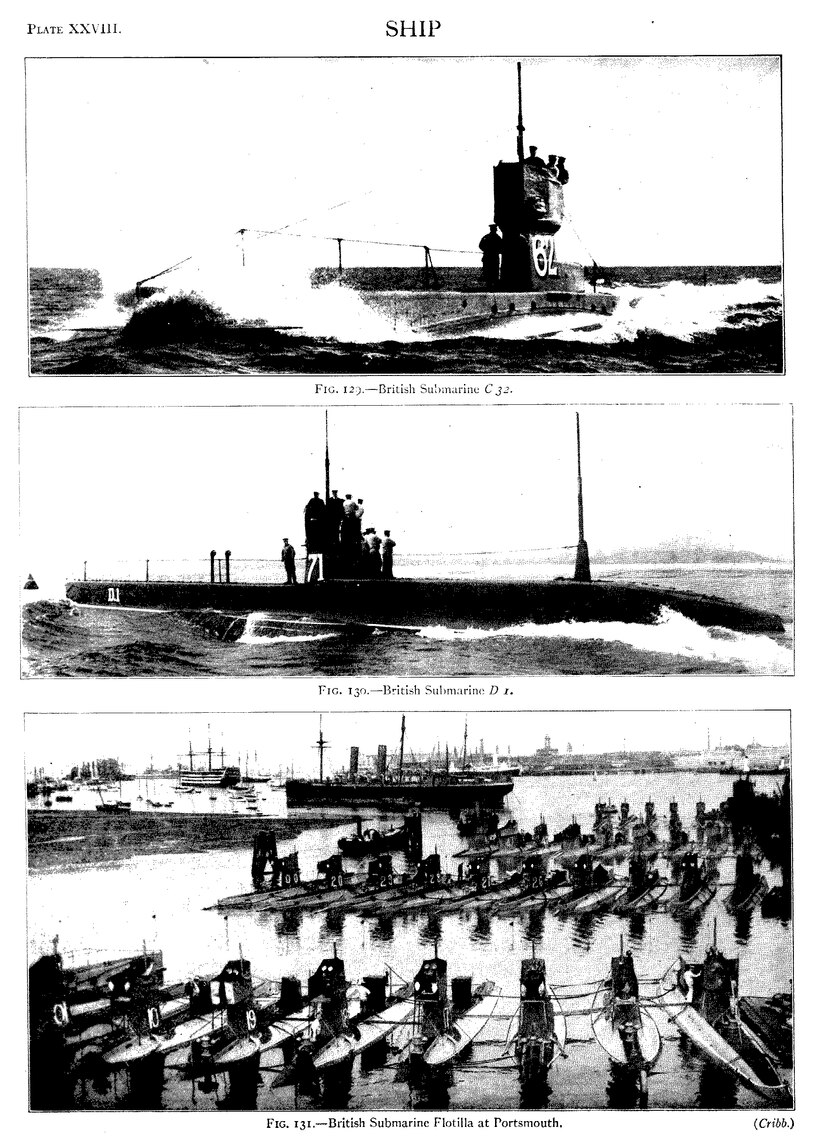
In response to an invitation for proposals for submarines, made by the U.S. government in 1887, designs by Holland and Nordenfeldt were submitted. After much consideration the proposals of the former designer were accepted, and formed the basis of the designs for the “Plunger,” the “Holland” and the six vessels of the “Adder” class. From what has been already stated, the criticism of Admiral Hichborn (chief constructor of the U.S. navy) will be understood when he characterizes Holland’s method as a “steering-under” or “diving” device, and Nordenfeldt’s as a “down-haul” or “sinking” design. The great majority of modern boats are worked by the Holland method. The “Plunger” was authorized in 1903; she has a length of 85 ft., diameter 1112 ft., light displacement 154 tons and load displacement 168 tons; she is of sufficient strength for a submergence of 75 ft., and when wholly submerged has a margin of buoyancy of 14 ton. In addition to her horizontal rudders for diving, she has two down-haul screws, fitted in opposition to Mr Holland’s recommendations; she may therefore be said to be a combination, for diving purposes, of both the Holland and the Nordenfeldt designs. The “Plunger’s” main engines are used for propulsion when she is navigated at the surface of the water. As originally designed they were triple-expansion steam engines, driving triple screws, but have since been altered to gasolene internal-combustion engines driving a single screw. These engines are also used for charging electric accumulators, from which alone motive-power can be obtained when the boat is submerged. The current for charging the accumulators is obtained from a dynamo of 70 H.P., which can always be run in the awash condition to keep the accumulators fully charged. In the awash condition, when the boat is otherwise air- and water-tight, communication is kept up with the outer air by means of ducts and a smoke-pipe, the former bringing in air for combustion and respiration, and the latter carrying off deleterious products of all kinds. For submergence special fittings are used to close these ducts and pipes, and to stop the gasolene generator. The main engine is then no longer available, and for propulsion power is drawn from the accumulators, the dynamo thus becoming a motor which derives current from the accumulators and itself drives the screw-shaft. As was the case with Mr Holland’s earlier boats, great attention is given to automatic control of weights, and water-ballast is admitted to compensate for any change, such as would be produced by the discharge of a torpedo. With her original machinery the “Plunger” was to have had a surface speed of 15 knots; her anticipated speed awash or submerged is now 8 knots. To assist in determining the boat’s direction a camera lucida is ordinarily provided, but for correcting this Mr Holland prefers trusting to observations made during occasional rises to the surface; for this purpose the boat is provided with a conning tower 4 ft. high, protected with 4-in. steel. The “Plunger” is armed with Whitehead torpedoes, and has two tubes for discharging them. After many trials it was at last decided to build a repeat of the “Adder” to take her place, and this second “Plunger” was completed in 1903. The “Holland” is a smaller boat, having a length of about 54 ft., and was purchased in 1900, The official report on this vessel is that “she has shown herself capable of such perfect control in the vertical plane that she may be kept whilst moving within a few inches of any desired depth, and that she may be brought to the surface and submerged again in a very short time.” A good idea of the general form of the “Holland” may be obtained from figs. 122, 123, 124 and 125 (Plate XXVII.), the last three of which represent this vessel when undergoing trials to test her driving qualities.

Fig. 126.—Plan of the U.S. “Adder” (reproduced by permission of Admiral Hichborn). A, storage batteries; B, gas-engine;
C, dynamo and motor; D, water-tight compartments; E, main ballast tanks; F, air-flasks; G, gasolene tank; H, expulsion tube.
The design of the six submersibles of the “Adder” class is shown in fig. 126. They are of the following dimensions: length 63 ft. 4 in., diameter 11 ft. 9 in.; displacement for surface running 104 tons; submerged displacement 120 tons. The main features of this class are the same as for the “Plunger.” The shell-plating is 716 in. in thickness, and the frames 312 in. by 3 in., with a spacing of 18 in. The main machinery is a four-cylinder single-acting balanced Otto gasolene engine, which at 360 revolutions will develop 160 H.P. and give the boat a speed of about 8 knots. For propulsion in the submerged condition an electric motor is used, working at 800 revolutions, and giving a speed of 7 knots, a single left-handed propeller being employed. The current for the motor is provided by storage batteries capable of supplying 70 H.P. for four hours; and these batteries are charged by the main engine. The requisite air supply is obtained when the vessel is at the surface, and is stored under a pressure of 2000 ℔ by a pump driven by gearing off the main engine or main motor. Air at a pressure of 50 ℔ is used for the expulsion of torpedoes, and the same agent, at various degrees of pressure, works the trimming and ballast tanks and some parts of the machinery; while the exhaust air from the latter subserves the purpose of ventilation. The vessel is fitted with power and hand-steering gear, and there are automatic devices for securing a constant depth during submergence. Five Whitehead torpedoes, 45 cm. (about 18 in.) in diameter and 11 ft. 8 in. long, are provided, and there is one expulsion tube placed forward about 2 ft. below the light water-line.
The French submarine boat' “Plongeur” has already been mentioned. A further advance in this direction was made in France in 1881, when a small submarine was completed by M. Goubet at Paris. An inspection of this vessel led to an stem order for the mechanism of a number of boats from this engineer for the Russian government, and several sets were builtGoubet system. and delivered early in 1883. The length of a boat constructed by M. Goubet in 1885 was 16 ft. 5 in.; it had an oval section 5 ft. 9 in. in depth and 3 ft. 3 in. in breadth, and tapered to a point at each end. A longitudinal section of the boat is represented by fig. 127. The main portion of the hull was of bronze, cast in one piece, and at the centre of its length it was surmounted by a large dome having seven glazed openings. There was just sufficient room for an officer and a. man seated back to back within it, their eyes in this position being level with the glass windows of the dome. All valves and other mechanism requiring regulation were brought within reach of these occupants, so that no movement on their part was required which might affect the trim; a reservoir of compressed air supplied the means of respiration, and an air-pump removed the vitiated atmosphere. The motive-power was furnished by accumulators, the electric energy stored therein driving a screw propeller by means of a motor. No means of recharging these accumulators when exhausted was provided on board. Submersion was effected by admitting water into tanks divided by transverse bulkheads at sufficient intervals to prevent the surging of the water in the fore and aft direction. A pump expelled this water again when desired, and at safety-weight attached to the bottom of the boat was ready for detachment in the presence of danger. A pressure gauge indicated the depth of water reached, and the officer could regulate the opening of the inlet valves or the action of the pumps to maintain or vary this depth as desired. For controlling the boat in a horizontal direction a specially devised pendulum was employed, by means of which a clutch was moved, and a constantly running shaft was thrown into gear with a pump as soon as the boat departed appreciably from the horizontal plane. The action of the pump was reversible, and the clutch engaged it always in such a way that it drew water from a tank at the low end of the boat, and delivered it to a tank at the high end. Several other devices of great ingenuity were employed in the boat; notably a special form of universal joint introduced into the line of shafting. At the after end, close to the propeller, this universal joint was fitted in such a way that the screw could be set at an angle to the line of motion, and steering effected without the aid of a vertical rudder. A torpedo containing 100 ℔ of dynamite or other explosive was carried outside the hull, and secured by a catch joint. This torpedo, on the submarine boat being manœuvred into position, could be thrown off and allowed to rise and attach itself, by means of spikes, to some vulnerable part of the ship doomed to destruction. Retiring then to a safe distance, the submarine boat could explode the torpedo by the agency of an electric current.

Fig. 127.—Section of Goubet Submarine Torpedo-boat.
Working in the light of his now considerable experience, M. Goubet built several other boats. These were of larger dimensions, having a length of 27 ft.; their material was also bronze, and they were cast in three pieces, the centre one having a thickness of 1 in., while the others were reduced to a little more than 12 in. at the ends. Possessing to a large extent the same contrivances as their predecessor, these improved boats were fitted also with an automatic apparatus for regulating the depth of submersion. In this regulator a piston is moved along a cylinder by the rotation of a rod with a screw thread cut in it, and so increases or diminishes the amount of water in the cylinder. The movement of the piston is effected by a small motor, and the direction of action of the motor is regulated by a commutator placed in juxtaposition to a pressure gauge. When the depth of submersion is too small, current is supplied to move the piston so as to admit more water; when the depth is too great, current is supplied in the opposite direction, and water is expelled. The speed attained by this boat was from 5 to 6 knots. Smaller boats of this type have been built for propulsion by manual power, but, however perfect the mechanism, the range of action of a submarine dependent on man-power for propulsion is very limited. Recent Goubet boats are being built, with motive-power, which it is proposed to carry on board ship and lower from davits when required.
The “Gymnote” was constructed at Toulon in 1888. She is a steel vessel, with a length of 59 ft. and a displacement of 30 tons; being of an experimental character only, she has no weapon of attack. The maximum speed obtainable is 8 knots. The designs of the “Gustave Zédé” and of the “Morse” were both based on those of the “Gymnote,” the former having a length of 148 ft. and a displacement of 263 tons. In both of these the hull is of bronze; one great advantage of this metal being that, like the bronze of the Goubet boats, it is non-magnetic in character, and cannot therefore disturb the equilibrium of the compass. With their large dimensions they were intended to be formidable engines of war, and were furnished for attack with Whitehead torpedoes; of these latter they each carry three of 45 cm. (nearly 18 in.) diameter, discharging them by means of a torpedo tube. The “Morse” and the “Gustave Zédé,” like the “Gymnote,” possess only electric means of propulsion, the power being derived from batteries of accumulators. No power is provided in the vessels by which the accumulators can be recharged, so that the radius of action of these boats is necessarily very limited. The “Narval,” designed by M. Laubeuf, and the outcome of a general competition in 1897. has a length of 112 ft. and a total displacement of 200 tons. She was built at Cherbourg in 1898, and is furnished with a triple-expansion steam engine, obtaining its steam from a water-tube boiler of special form and heated by petroleum. As in the American submarines, this engine propels the boat when at the surface, and also drives a dynamo which recharges accumulators, the latter giving the reserve power for use in the submerged condition. A speed of 11 knots is obtained at the surface, and 8 knots when submerged. A new departure in the “Narval” is her double hull, the inner shell of which is of steel plate of sufficient thickness to resist any water-pressure to which the oat may be subjected, and the outer shell, placed at varying distances from the inner, forms a protection to the inner against attack. An armoured dome surmounts the boat, cutting through the external shell and carrying a short and narrow telescopic funnel, which, as in the case of the American boats must be withdrawn preparatory to diving. Control in the vertical direction is obtained, when diving, by the use of two pairs of horizontal rudders, placed symmetrically–one pair forward, the other aft. By the above arrangement it is claimed that the horizontal direction of the boat is ensured, the American course of inclining the axis of the boat when diving being considered open to such grave objections that it is desirable to avoid it.
The early American boats of the “Holland” type, and the French boats built in the last decade of the 19th century were the earliest really practical submarine boats, in the sense that unlike the boats which preceded them they were instruments of war which could be used by ordinary trained crews with the average chances of success and failure which attend all warlike operations. They owe their practicability not to any discovery of the method of controlling the movements of a boat beneath the surface of the water, as has been sometimes supposed, since the ordinary method of steering by means of a rudder or a combination of rudders perfectly analogous to that used for manœuvring a ship in the horizontal plane was well known and had been applied to steering submarines in the vertical plane before; but principally to the perfection of the accumulator cell as a means of storing energy for propulsion without the expenditure of air or other weight contained in the boat, and to the introduction of the optical tube. This latter instrument is a telescope with the optical axis twice bent through a right angle by totally reflecting prisms or mirrors; and under diverse forms and various names, such as periscope, cleptoscope, hyphydroscope, omniscope, &c., it affords the only practical means by which objects on the surface-of the water can be seen at a distance from the interior of a submerged vessel. The problem of providing means for seeing at a distance through the water still awaits solution, and when solved, if it ever should be, will enormously add to the power of submarine boats as weapons of war.
By far the greater number of submarine boats in existence in 1910 were developments through a process of continuous experiment and improvement of the “Gymnote” and of the early Holland boats, although the process of evolution had been so rapid and extensive that the parentage of these modern boats is barely recognizable. There are, however, a considerable number of submarines built by the Lake Submarine Boat Co. of Bridgeport, U.S.A., in the service of various naval powers. These boats are designed by Mr Simon Lake, who was also a pioneer in submarine boat construction, contemporary with Mr J. P. Holland in the United States of America. His earliest boat, the “Argonaut,” was intended rather for running along the bottom in shallow water than for ordinary navigation; and for sending out divers rather than for discharging torpedoes. For this purpose it was fitted with wheels for running along the bottom and with an air-tight chamber having a hatch at the bottom which could be opened when the air pressure in the chamber was made equal to that of the water outside. These features are still retained in many of the modern Lake boats, though these boats are now constructed like all other submarines, primarily for the purpose of submarine navigation.
Other boats which should be mentioned as laying claims to distinctive features in matters of detail are those built by the Fiat San Giorgio Company of Spezia, designed by Colonel Laurenti, and those built by the Germania Werft of Kiel, which are understood to embody the patents of M. d’Equevilley. The Russian government also possesses several boats generally regarded as of a distinctive type designed by M. Drzwiecki.
Perhaps the most outstanding distinction between different submarine boats is the amount of their submerged displacement which is devoted to carrying water ballast. This, of course, measures their reserve of buoyancy in the surface condition, which in different examples of boats varies from as little as 5% to as much as 60% of their surface displacement. It is obvious that, the more water ballast carried, the less of some other weight of machinery or equipment can be carried on a given submerged displacement, and the whole problem resolves itself into making the compromise which will best meet the requirements of the service for which the boat is intended. This fact has sometimes been lost sight of in discussions on this subject, which have tended sometimes to proceed on the assumption of a radical difference in character between boats of high reserve of buoyancy and those of low reserve, even to the extent of giving them the different names of “submersible” and “submarine.” Another technical point in the design of submarines which has frequently been the subject of non-technical discussion is the desirability or otherwise of “bow-rudders” or “hydroplanes.” This question depends on the form of the boat, and the manner in which it is proposed to handle her, and is unsuitable for discussion except in relation to the ascertained tendencies of a particular form under the vertical hydrodynamical forces which are set up by its propulsion through the water.
Similar considerations apply to the questions whether a submarine boat should have a separate means of propulsion for surface-running distinct from that fitted for submerged propulsion, and if so, whether it should consist of steam or internal-combustion engines. On account of the very limited capacity of even the best modern electric accumulator, any submarine which is intended to have a considerable radius of action must necessarily have heat engines of some description for surface propulsion and for charging batteries.
As to the type of heat engine, France was the only country which in 1910 had fitted steam engines in recently built submarines; and the general tendency was undoubtedly to use internal-combustion engines, of which those burning heavy oil are much less expensive in working than those using gasolene.
The general tendency in 1910 was to increase the size of submarine boats. Improvements in the design, apart from increase in size, depend principally on the improvements which may be made in the internal-combustion engines required for their surface propulsion, and in the improvement or possible elimination of the electric accumulators and motors for submerged propulsion, the weight of which is exceedingly great for the power obtained when compared with that which is obtained from heat engines.
It is the practice of all countries to keep secret the really important details of their submarine boats, to an even greater extent than those of ordinary warships. Some particulars, however, of the newer submarines of different countries are given below principally to illustrate the progress in size and power.
In France, in 1901, M. Romazotti, already referred to as the designer of the “Morse" and “Gustave Zédé,” produced two other boats, the “Français” and “Algérien,” similar to the “Morse.” Four vessels, the “Siréne,” “Triton,” “Silure,” and “Espadon,” of a modified “Narval,” type, were built from M. Laubeuf’s designs in 1901; two others of a similar type, the “Aigrette” and “Cigogne,” but of 170 tons surface displacement, were built in 1904, and two other still larger boats, the “Circé” and “Calypso,” in 1905. These, two boats are (155 ft. long, 16 ft. beam, 10 ft. draught) of 350 tons displacement on the surface 480 tons submerged. Two Diesel heavy oil engines are fitted to give 1134 knots speed on the surface and two electric motors for use when submerged. Four boats of the “Gnôme” type, of 200 tons and 280 H.P. and 135 ft. in length, designed by M. Maugas, were commenced in 1899. In 1901 twenty small submarines of the “Naiade” type were commenced to M. Romazzotti’s design; they are 76 ft. in length and of 68 tons displacement, and have a surface speed of 8 knots and a speed of 4·5 knots when submerged. Their motive-power is electrical both for surface and submerged propulsion, except in the case of two boats which are provided with benzol motors for surface work. From 1905 to 1909, 34 boats of the “Pluviose” type of twin-screw submersibles designed by M. Laubeuf were laid down; they have a displacement on the surface of 392 tons, and have engines of 700 H.P. and a speed of 12 knots on the surface, and 440 H.P. and a speed of 734 knots when submerged. Eighteen boats of the class have triple-expansion engines, and each of the remainder has two Diesel heavy oil motors for surface propulsion, while all have electric motors for use when submerged. Some of the steam-driven boats have traversed 730 m. in 82 hours, while the “Papin” with oil motors ran 1200 m. from Rochefort to Oran in six days without calling at any intermediate port. In fig. 128 (Plate XXVII.) is shown the “Vendemiaire,” one of the boats of this class. The twin screw submarines of the “Emeraude” class, six in number, designed by M. Maugas and laid down in 1906, are of approximately the same displacement as the “Pluviose” class and of about the same speed; their motive-power consists of two Diesel heavy oil engines on surface and electric motors when submerged. A considerable advance in length and displacement was made in 1907, when the “Mariotte,” 216 ft. in length, 522 tons displacement on the surface, and 615 tons submerged, the “Archimède,” 199 ft. in length and 568 tons displacement on the surface and 797 tons submerged, and the “Admiral Bourgois.” 181 ft. in length and 555 tons surface displacement, were laid down. The H.P.s of these three submersibles are 1400, 1700 and 1500 respectively at the surface, giving a speed of 15 knots (submerged speed 10 knots).
After the completion of the last boat of the “Adder” class already referred to, a period of about three years elapsed before the acquisition for the United States navy of any additional submarine boats. The “Octopus,” which underwent extended trials in 1907, was designed by the Electric Boat Company, the successors of the Holland Boat Company, and marked a great advance in all respects over the earlier boats. She is a twin-screw boat, having two torpedo tubes instead of one, as in the previous boats; she is of about 273 tons displacement submerged and 255 tons on the surface, and is credited with maximum trial speeds of 11 knots on the surface and 10 knots submerged. Three other boats, the “Cuttlefish,” “Tarantula” and “Viper,” generally similar to but somewhat smaller and less powerful than the "Octopus,” were also completed during 1907 and 1908, and the “Snapper,” “Bonita,” “Stingray” and “Tarpon,” of the same size as the “Octopus,” in 1909. The “Salmon,” a boat similar to the “Octopus,” but of 278 tons displacement on the surface, 360 tons submerged and carrying four torpedo tubes, was completed in 1910, and is credited with trial speeds of 13 knots on the surface and 912 knots submerged. In July 1910 this boat made the ocean passage of about 700 to 800 m. from Quincy, Mass., to Kingston, Bermuda, in four days, and returned in about the same time, proving herself remarkably seaworthy for so comparatively small a boat in the rough weather encountered. Several similar boats were in 1910 under construction.
In 1900 Great Britain ordered five submarine boats from Messrs Vickers, Sons & Maxim, at Barrow, who, by arrangement with the Electric Boat Company of New York, were enabled to embody in their designs all the features of the Holland boats of the “Adder” class, which these first British submarines resembled in size and most other respects, the length being about 63 ft. and submerged displacement 120 tons. Subsequent British submarines of the A, B and C classes were designed by Messrs Vickers, Sons & Maxim under instructions from the Admiralty. The progress in size and power has been continuous, and the departure from the original “Holland” type more and more marked with each successive new design. Table XX. indicates the various steps. All the boats there mentioned, except A13, which has heavy oil engines, are fitted with gasolene engines for surface propulsion. D1, which also has heavy oil engines, was completed in September 1909, and was the first of a new series of boats for the design of which Sir Philip Watts was personally responsible. She passed through her trials, and seven similar boats were in 1910 under construction. Fig. 129 (Plate XXVIII.) gives a view of C32, while fig. 130 shows D1 under weigh on the surface, and fig. 131 a flotilla in Portsmouth Harbour.
| Name or Class of Boat. |
Year of Completion. |
Length. | Breadth. | Submerged Displacement. |
Horse- Power of Engines. |
Speed on Surface. |
| Feet. | Tons | Knots. | ||||
| A1 | 1903 | 100 | 11′ 9″ | 206 | 350 | 9 |
| A2–A4 | 1904–1905 | 99 | 12′ 8″ | 205 | 450 | 1012 |
| A5–A12 | 1905–1906 | 99 | 12′ 8″ | 205 | 600 | 1112 |
| A13 | 1906–1907 | 99 | 12′ 8″ | 205 | 500 | 1112 |
| B1–B11 | 1905–1907 | 135 | 13′ 6″ | 314 | 600 | 1212 |
| C1–C17 | 1907–1909 | 135 | 13′ 6″ | 314 | 600 | 1212 |
| C19–C38 | 1908–1910 | 135 | 13′ 6″ | 320 | 600 | 1212 |
Russia purchased the Lake demonstration boat “Protector” in 1904. This boat is 65 ft. long, 115 tons displacement on the surface and 170 tons submerged. The surface speed is stated to be 9 knots and the submerged 6 knots. A larger boat, of 135 tons displacement—the “Simon Lake”—was also purchased, and four others of the same size built in 1904–1905. In 1907 another small “Lake” boat of 110 tons was obtained, and in 1908 and 1909 seven larger vessels, 125 ft. long, 14 ft. beam, 450 tons on surface, 500 tons submerged, 16 knots speed on surface with petrol engines, and 612 knots submerged, with electric motors. Of the “Holland" type Russia has obtained a considerable number; fifteen of these are from 106 to 175 tons on the surface, and one is 184 ft. long, 12 ft. beam, 11 ft. deep and 360 tons on the surface. She has also obtained three boats of the “Germania” type, 131 ft. long, 197 tons on the surface, as well as a specimen of a small submarine of 17 tons hoisting weight driven by electric accumulators only, giving 8 knots on the surface and 6 knots submerged, and armed with one torpedo tube. The large boats of the “Lake” type are driven by engines of 1200 H.P., and are stated to carry an armament of two 3-pdr. and two machine guns in addition to their four torpedo tubes. Three of the Russian submarines under construction in 1910 were 500 tons displacement on the surface.
Germany did not build submarines until 1906, when U1 was launched at the Germania Works, Kiel. She is 139 ft. long, 11 ft. 9 in. beam, 7 ft. 9 in. draught and 240 tons on the surface, being slightly larger than the Russian boats built by the same firm. She is fitted with twin-screws driven by petroleum motors of 450 H.P., giving a speed of 11 knots on the surface, and electric motors of 200 H.P., giving a speed of 9 knots when submerged. Three 18-in. torpedoes are carried, one bow tube only being provided. In 1908–1909 three larger boats were built at Dantzig, and in 1909–1910 three of 600 tons displacement at the Germania works. The boats were reported to have made very long sea. passages without escort.
Japan commenced building “Holland” boats in 1905. The first live were 87 ft. in length and 125 tons displacement. Two smaller boats of 86 tons were also built. In 1908 two boats of 320 tons were built at Barrow, and dispatched by steamer to Japan; and three similar boats were in 1910 being built in Japan.
In 1894 Italy launched the “Delfino,” a single-screw boat of 105 tons and 150 H.P. The type has not been repeated, but in 1905 a fresh start was made with three boats of the “Glauco” type, twin-screw boats of 150 tons on the surface, 175 tons submerged, H.P. on surface 600 to 700, speed 14 knots on surface and 8 knots submerged. In 1908 three similar but larger boats followed, the largest being the “Foca,” 137 ft. 9 in. long, 14 ft. beam, displacement 175 tons, 900 H.P. and 15 knots speed in surface condition, 225 tons displacement, 200 H.P. and 9 knots when submerged, fitted with two 18-in: torpedo tubes. In 1910 six similar but larger boats were laid down at Spezia.
The increased interest in naval matters in Austria is shown by the expenditure on submarines as well as on battleships. In 1907 two boats of the “Lake” type 100 ft. long, 250 tons submerged, were laid down at the government dockyard at Pola; between that date and 1910 two boats of modified “Holland” type, 138 ft. long, 300 tons submerged and 12 knots surface speed, were built at Fiume, and two of the “Germania” type ordered from Kiel.
The Swedish government began by building a submarine boat, the “Hojen,” which is understood to have resembled the early “Holland” designs. In 1910 the “Hvalen,” a boat similar to the latest Italian submarines, was built for the Swedish government by the Fiat San Giorgio Company at Spezia, and acquired some notoriety by making the voyage from Spezia to Stockholm without escort, including a longest run of about 700 m. from Spezia to Cartagena.
The “Dykkeren,” a submarine of the “Laurenti” type, but entirely electrically propelled both at the surface and submerged, was built by the Fiat San Giorgio Company at Spezia for the Danish government in 1909. She is credited with a maximum speed of 12 knots on the surface and 8 knots submerged, but, depending entirely on the energy stored in electric accumulators, her radius of action is necessarily restricted.
Fleet Auxiliaries.—Various types of auxiliaries are provided in the principal navies to perform services of a supplementary, though frequently important character. In many cases fighting vessels of the older classes have been converted and adapted as well as is practicable for these services, but in other cases new vessels have been built or arrangements made with owners of suitable merchant ships for the adaptation and use of those ships when required by the navies. Amongst such auxiliaries the following are found in the British navy:—Mine-laying vessels—second-class cruisers of the Apollo class modified for the purpose; fleet-repair ships—the modified merchant-built vessels “Assistance” of 9600 tons displacement and the “Cyclops” of 11,300 tons; distilling vessel—“Aquarius” of 3660 tons, a modified merchant vessel, and a large number of tank vessels such as the, “Provider” of 395 tons, specially built for distributing fresh water; depot and repair ships for destroyers—the modified cruisers “Blake,” “Blenheim,” “Leander” and “St George,” and the modified merchant vessels “Hecla” and “Tyne”; depot ships for submarines—the modified cruisers “Bonaventure,” “Thames,” &c., and the repair ship “Vulcan,” as well as a new vessel the “Maidstone,” of 3600 tons, laid down at Scott's Yard, Greenock, in 1910; oil tank vessels—the merchant built vessels “Petroleum,” of 9900 tons and “Kharki” of 1430 tons, and a new vessel, the “Burma” of 3870 tons, laid down at the Greenock Dockyard Co.’s Yard in 1910. The hospital ship “Maine” of 4540 tons—was fitted up for service of the United States in the Spanish-American War, and was presented to the British government in 1901 by the Atlantic Transport Co.
Besides the foregoing, arrangements are made for fitting up fast vessels such as the “Mauretania” and “Lusitania” with a number of 6-in. or other Q.F. guns for service as merchant cruisers in time of war, when they would be used as ocean-going scouts, or for the protection of trade routes. Corresponding arrangements are made by several other countries, while in Russia and Japan special mercantile cruisers have been built under the title of Volunteer steamers. A full account of the Russian Volunteer Fleet is to be found in a paper read by Mr H. Rowell at the Institute of Naval Architects 1905, later vessels being described in Engineering, 11th March 1910, and an account of the Japanese Volunteer vessels will be found in International Marine Engineering, June 1909.
The writer is indebted to Mr J. H. Narbeth, M.V.O., for valuable assistance in preparing this article. (P. Wa.)
- ↑ The raft of Ulysses described in Homer (Od. v.) must have been of this class.
- ↑ See Captain Cook’s account of the Friendly Islands, La Pérouse on Easter Island, and Williams on the Fiji Islands.
- ↑ Compare the planks upon the Egyptian war galleys, added so as to protect the rowers from the missiles of the enemy.
- ↑ It is curious that these two methods should still survive, and be in use, in the construction of light racing 8-oared boats. Some of these are built ribs first, and skin laid on afterwards; others, skin laid on moulds and framework first, and ribs inserted in the shell when turned over.
- ↑ See Rawlinson, Ancient Monarchies, vol. ii. p. 176.
- ↑ In Vitruvius 1, 2, 4 the MSS. give Dipheciaca (or Difeciaca), which is an unknown word. Many of the editions read ΔΙΠΗΧΑΙΚΗ, an emendation which commends itself as consonant with probability, though in itself conjectural. (We may suggest the reading ΔΙΠΗΧΑΙΚΑ, by which the scribe’s error would be reduced to EC for X.)
- ↑ Merivale, Hist. of Romans under the Empire, c. 28.
- ↑ See Sir G. V. Holmes, Ancient and Modern Ships, i. 87, to which the writer is indebted for many of the details concerning modern vessels.
- ↑ A very complete account of this vessel was given by her designer, Mr W. E. Smith, C.B., in the Transactions of the Institution of Naval Architects (1905).
- ↑ The original propeller used by the “Rattler” is now to be seen in the Victoria and Albert Museum.
- ↑ “Titanic,” launched October 10, 43,500 tons.
- ↑ Sister vessel “Dakota” was lost on Japan coast March 1907.
- ↑ A third vessel of same size was being completed.
- ↑ See letters of the earl of Rosse on this subject, Transactions of Inst. of Naval Architects for 1908.
- ↑ The “Fury” was modified and renamed “Dreadnought” before being launched.
- ↑ The “Victoria” was accidentally rammed and sunk by the “Camperdown” during the Mediterranean manœuvres of 1893.
- ↑ These two vessels were afterwards purchased by the British government and became the “Swiftsure” and “Triumph” (fig. 69. Plate XVIII.).
- ↑ The gun and armour diagrams and many particulars of modern vessels are taken by permission from Brassey’s Naval Annual.
- ↑ She was launched on the 20th of August 1910.
- ↑ From the “Trafalgar” to the “Royal Sovereign,” and from the “Duncan” to the “King Edward VII.,” increases in each case of 17% were accepted.