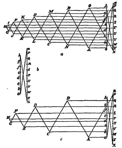
figure. The direction of the force in each member is easily ascertained by proceeding in the manner above described. A single known force in a polygon determines the direction of all the others, as these must all correspond with arrows pointing the same way round the polygon. Let the arrows be placed on the frame round each joint, and so as to indicate the direction of each force on that joint; then when two arrows point to one another on the same piece, that piece is a tie; when they point from one another the piece is a strut. It is hardly necessary to say that the forces exerted by the two ends of any one member must be equal and opposite. This method is universally applicable where there are no redundant members. The reciprocal figure for any loaded frame is a complete formula for the stress on every member of a frame of that particular class with loads on given joints.
Consider a Warren girder (fig. 68), loaded at the top and bottom joints. Fig. 69 b is the polygon of external forces, and 69 c is half the reciprocal figure. The complete reciprocal figure is shown in fig. 69 a.
The method of sections already described is often more convenient than the method of reciprocal figures, and the method of influence lines is also often the readiest way of dealing with braced girders.
35. Chain Loaded uniformly along a Horizontal Line.—If the lengths of the links be assumed indefinitely short, the chain under given simple distributions of load will take the form of comparatively simple mathematical curves known as catenaries. The true catenary is that assumed by a chain of uniform weight per unit of length, but the form generally adopted for suspension bridges is that assumed by a chain under a weight uniformly distributed relatively to a horizontal line. This curve is a parabola.
Remembering that in this case the centre bending moment Σwl will be equal to wL2/8, we see that the horizontal tension H at the vertex for a span L (the points of support being at equal heights) is given by the expression
or, calling x the distance from the vertex to the point of support,
H = wx2/2y,
The value of H is equal to the maximum tension on the bottom flange, or compression on the top flange, of a girder of equal span, equally and similarly loaded, and having a depth equal to the dip of the suspension bridge.
Consider any other point F of the curve, fig. 70, at a distance x from the vertex, the horizontal component of the resultant (tangent to the curve) will be unaltered; the vertical component V will be simply the sum of the loads between O and F, or wx. In the triangle FDC, let FD be tangent to the curve, FC vertical, and DC horizontal; these three sides will necessarily be proportional respectively to the resultant tension along the chain at F, the vertical force V passing through the point D, and the horizontal tension at O; hence
H : V = DC : FC = wx2/2y : wx = x/2 : y,
hence DC is the half of OC, proving the curve to be a parabola.
The value of R, the tension at any point at a distance x from the vertex, is obtained from the equation
R2 = H2+V2 = w2x4/4y2+w2x2,
or,
Let i be the angle between the tangent at any point having the co-ordinates x and y measured from the vertex, then
Let the length of half the parabolic chain be called s, then
The following is the approximate expression for the relation between a change ∆s in the length of the half chain and the corresponding change ∆y in the dip:—
s+∆s = x+(2/3x) {y2+2y∆y+(∆y)2} = x+2y2/3x+4y∆y/3x+2∆y2/3x,
or, neglecting the last term,
and
From these equations the deflection produced by any given stress on the chains or by a change of temperature can be calculated.

|
| Fig. 71. |
36. Deflection of Girders.— Let fig. 71 represent a beam bent by external loads. Let the origin O be taken at the lowest point of the bent beam. Then the deviation y = DE of the neutral axis of the bent beam at any point D from the axis OX is given by the relation
d2ydx2 = MEI,
where M is the bending moment and I the amount of inertia of the beam at D, and E is the coefficient of elasticity. It is usually accurate enough in deflection calculations to take for I the moment of inertia at the centre of the beam and to consider it constant for the length of the beam. Then
dy/dx = 1EI Mdx
y = 1EIMdx2.
The integration can be performed when M is expressed in terms of x. Thus for a beam supported at the ends and loaded with w per inch length M = w(a2−x2), where a is the half span. Then the deflection at the centre is the value of y for x = a, and is
δ = 524 wa4EI
The radius of curvature of the beam at D is given by the relation
R = EI/M.


