| φ | η | Vo |
| 90° | 0.47 | 1.03 √2gH |
| 45° | 0.56 | 1.06 ” |
| 30° | 0.65 | 1.12 ” |
| 20° | 0.73 | 1.24 ” |
| 10° | 0.84 | 1.75 ” |
φ cannot practically be made less than 20°; and, allowing for the frictional losses neglected, the efficiency of a pump in which φ = 20° is found to be about .60.
§ 210. Case 2. Pump with a Whirlpool Chamber, as in fig. 210.—Professor James Thomson first suggested that the energy of the water after leaving the pump disk might be utilized, if a space were left in which a free vortex could be formed. In such a free vortex the velocity varies inversely as the radius. The gain of pressure in the vortex chamber is, putting ro, rw for the radii to the outlet surface of wheel and to outside of free vortex,

| if | k = ro / rw. |
The lift is then, adding this to the lift in the last case,
H={Vo2 − uo2 cosec2 φ + vo2 (1 − k2)} / 2g.
| But | vo2 = Vo2 − 2Vouo cot φ + uo2 cosec2 φ; |
| ∴ H = {(2 − k2) Vo2 − 2kVouo cot φ − k2uo2 cosec2 φ} / 2g. | (10) |
Putting this in the expression for the efficiency, we find a considerable increase of efficiency. Thus with
| φ = 90° and | k = 12, | η = 78 nearly, |
| φ a small angle and | k = 12, | η = 1 nearly. |
With this arrangement of pump, therefore, the angle at the outer ends of the vanes is of comparatively little importance. A moderate angle of 30° or 40° may very well be adopted. The following numerical values of the velocity of the circumference of the pump have been obtained by taking k = 12, and uo = 0.25√(2gH).
| φ | Vo | |
| 90° | .762 | √2gH |
| 45° | .842 | ” |
| 30° | .911 | ” |
| 20° | 1.023 | ” |
The quantity of water to be pumped by a centrifugal pump necessarily varies, and an adjustment for different quantities of water cannot easily be introduced. Hence it is that the average efficiency of pumps of this kind is in practice less than the efficiencies given above. The advantage of a vortex chamber is also generally neglected. The velocity in the supply and discharge pipes is also often made greater than is consistent with a high degree of efficiency. Velocities of 6 or 7 ft. per second in the discharge and suction pipes, when the lift is small, cause a very sensible waste of energy; 3 to 6 ft. would be much better. Centrifugal pumps of very large size have been constructed. Easton and Anderson made pumps for the North Sea canal in Holland to deliver each 670 tons of water per minute on a lift of 5 ft. The pump disks are 8 ft. diameter. J. and H. Gwynne constructed some pumps for draining the Ferrarese Marshes, which together deliver 2000 tons per minute. A pump made under Professor J. Thomson’s direction for drainage works in Barbados had a pump disk 16 ft. in diameter and a whirlpool chamber 32 ft. in diameter. The efficiency of centrifugal pumps when delivering less or more than the normal quantity of water is discussed in a paper in the Proc. Inst. Civ. Eng. vol. 53.
§ 211. High Lift Centrifugal Pumps.—It has long been known that centrifugal pumps could be worked in series, each pump overcoming a part of the lift. This method has been perfected, and centrifugal pumps for very high lifts with great efficiency have been used by Sulzer and others. C. W. Darley (Proc. Inst. Civ. Eng., supplement to vol. 154, p. 156) has described some pumps of this new type driven by Parsons steam turbines for the water supply of Sydney, N.S.W. Each pump was designed to deliver 112 million gallons per twenty-four hours against a head of 240 ft. at 3300 revs. per minute. Three pumps in series give therefore a lift of 720 ft. The pump consists of a central double-sided impeller 12 in. diameter. The water entering at the bottom divides and enters the runner at each side through a bell-mouthed passage. The shaft is provided with ring and groove glands which on the suction side keep the air out and on the pressure side prevent leakage. Some water from the pressure side leaks through the glands, but beyond the first grooves it passes into a pocket and is returned to the suction side of the pump. For the glands on the suction side water is supplied from a low-pressure service. No packing is used in the glands. During the trials no water was seen at the glands. The following are the results of tests made at Newcastle:—
| I. | II. | III. | IV. | ||
| Duration of test | hours | 2 | 1.54 | 1.2 | 1.55 |
| Steam pressure | ℔ per sq. in. | 57 | 57 | 84 | 55 |
| Weight of steam per water h.p. hour | ℔ | 27.93 | 30.67 | 28.83 | 27.89 |
| Speed in revs, per min. | 3300 | 3330 | 3710 | 3340 | |
| Height of suction | ft. | 11 | 11 | 11 | 11 |
| Total lift | ft. | 762 | 744 | 917 | 756 |
| Million galls. per day pumped— | |||||
| By Venturi meter | 1.573 | 1.499 | 1.689 | 1.503 | |
| By orifice | 1.623 | 1.513 | 1.723 | 1.555 | |
| Water h.p. | 252 | 235 | 326 | 239 | |
In trial IV. the steam was superheated 95° F. From other trials under the same conditions as trial I. the Parsons turbine uses 15.6 ℔ of steam per brake h.p. hour, so that the combined efficiency of turbine and pumps is about 56%, a remarkably good result.
 |
| Fig. 212. |
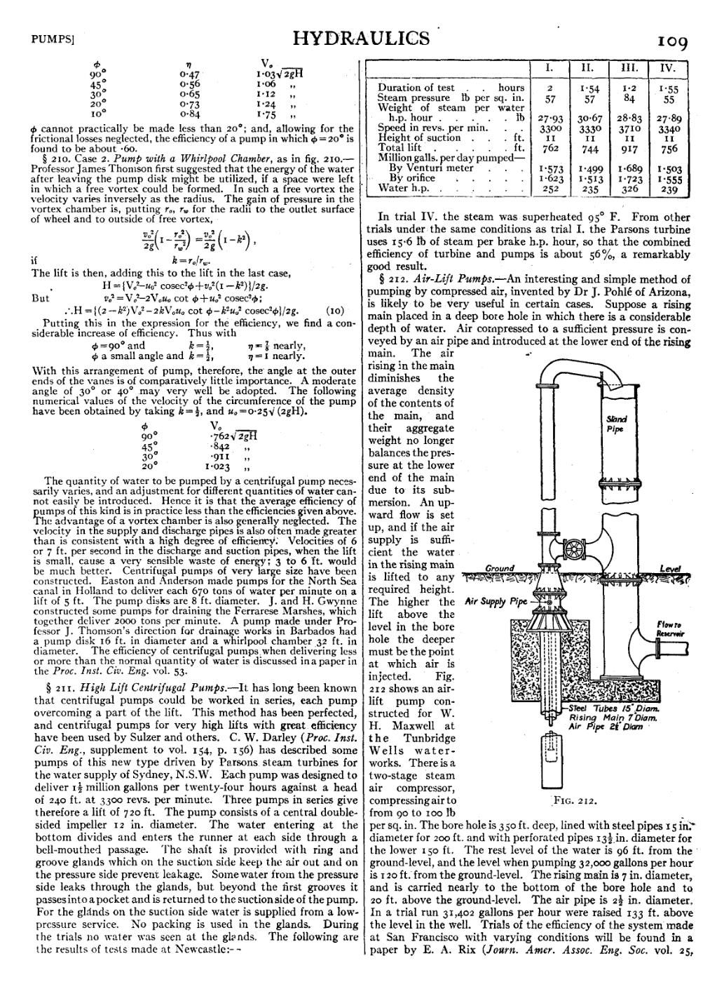
§ 212. Air-Lift Pumps.—An interesting and simple method of pumping by compressed air, invented by Dr J. Pohlé of Arizona, is likely to be very useful in certain cases. Suppose a rising main placed in a deep bore hole in which there is a considerable depth of water. Air compressed to a sufficient pressure is conveyed by an air pipe and introduced at the lower end of the rising main. The air rising In the main diminishes the average density of the contents of the main, and their aggregate weight no longer balances the pressure at the lower end of the main due to its submersion. An upward flow is set up, and if the air supply is sufficient the water in the rising main is lifted to any required height. The higher the lift above the level in the bore hole the deeper must be the point at which air is injected. Fig. 212 shows an airlift pump constructed for W. H. Maxwell at the Tunbridge Wells waterworks. There is a two-stage steam air compressor, compressing air to from 90 to 100 ℔ per sq. in. The bore hole is 350 ft. deep, lined with steel pipes 15 in. diameter for 200 ft. and with perforated pipes 1312 in. diameter for the lower 150 ft. The rest level of the water is 96 ft. from the ground-level, and the level when pumping 32,000 gallons per hour is 120 ft. from the ground-level. The rising main is 7 in. diameter, and is carried nearly to the bottom of the bore hole and to 20 ft. above the ground-level. The air pipe is 212 in. diameter. In a trial run 31,402 gallons per hour were raised 133 ft. above the level in the well. Trials of the efficiency of the system made at San Francisco with varying conditions will be found in a paper by E. A. Rix (Journ. Amer. Assoc. Eng. Soc. vol. 25,