For simplicity of calculation Rankine chose logarithmic curves for both the inner and outer faces, and they fit very well with the conditions. With one exception, however—the Beetaloo dam in Australia 110 ft. high—there are no practical examples of dams with logarithmically curved faces.
After Rankine, a French engineer, Bouvier, gave the ratio of the maximum stress in a dam to the maximum vertical stress as 1 to the cosine squared of the angle between the vertical and the resultant which, in dams of the usual form, is about as 13 is to 9.
During the last few years attention has been directed to the stresses—including shearing stresses—on planes other than horizontal. M. Levy contributed various papers on the subject which will be found in the Comptes rendus de l’Académie des Sciences (1895 and 1898) and in the Annales des Ponts et Chaussées (1897). He investigated the problem by means of the general differential equations of static equilibrium for dams of triangular and rectangular form considered as isotropic elastic solids. In one of these papers Levy formulated the requirement now generally adopted in France that the vertical pressure at the upstream end of any joint, calculated by the law of uniformly varying stress, should not be less than that of the water pressure at the level of that joint in order to prevent intrusive water getting into the structure.
These researches were followed by those of Messrs L. W. Atcherley and Karl Pearson, F. R.S.,[1] and by an approximate graphical treatment by Dr W. C. Unwin, F.R.S.[2] Dr Unwin took two horizontal planes, one close above the other, and calculated the vertical stresses on each by the law of uniformly varying stresses. Then the difference between the normal pressure on a rectangular element in the lower plane and that on the upper plane is the weight of the element and the difference between the shears on the vertical faces of that element. The weights being known, the principal stresses may be determined. These researches led to a wide discussion of the sufficiency of the law of uniformly varying stress when applied to horizontal joints as a test of the stability of dams. Professor Karl Pearson showed that the results are dependent upon the assumption that the distribution of the vertical stresses on the base of the structure also followed the law of uniformly varying stress. In view of the irregular forms and the uncertainties of the nature of the materials at the foundation, the law of uniformly varying stress was not applicable to the base of the dam. He stated that it was practically impossible to determine the stresses by purely mathematical means. The late Sir Benjamin Baker, F.R.S., suggested that the stresses might be measured by experiments with elastic models, and among others, experiments were carried out by Messrs Wilson and Gore[3] with indiarubber models of plane sections of dams (including the foundations) who applied forces to represent the gravity and water pressures in such a manner that the virtual density of the rubber was increased many times without interfering with the proper ratio between gravity and water pressure, and by this means the strains produced were of sufficient magnitude to be easily measured.
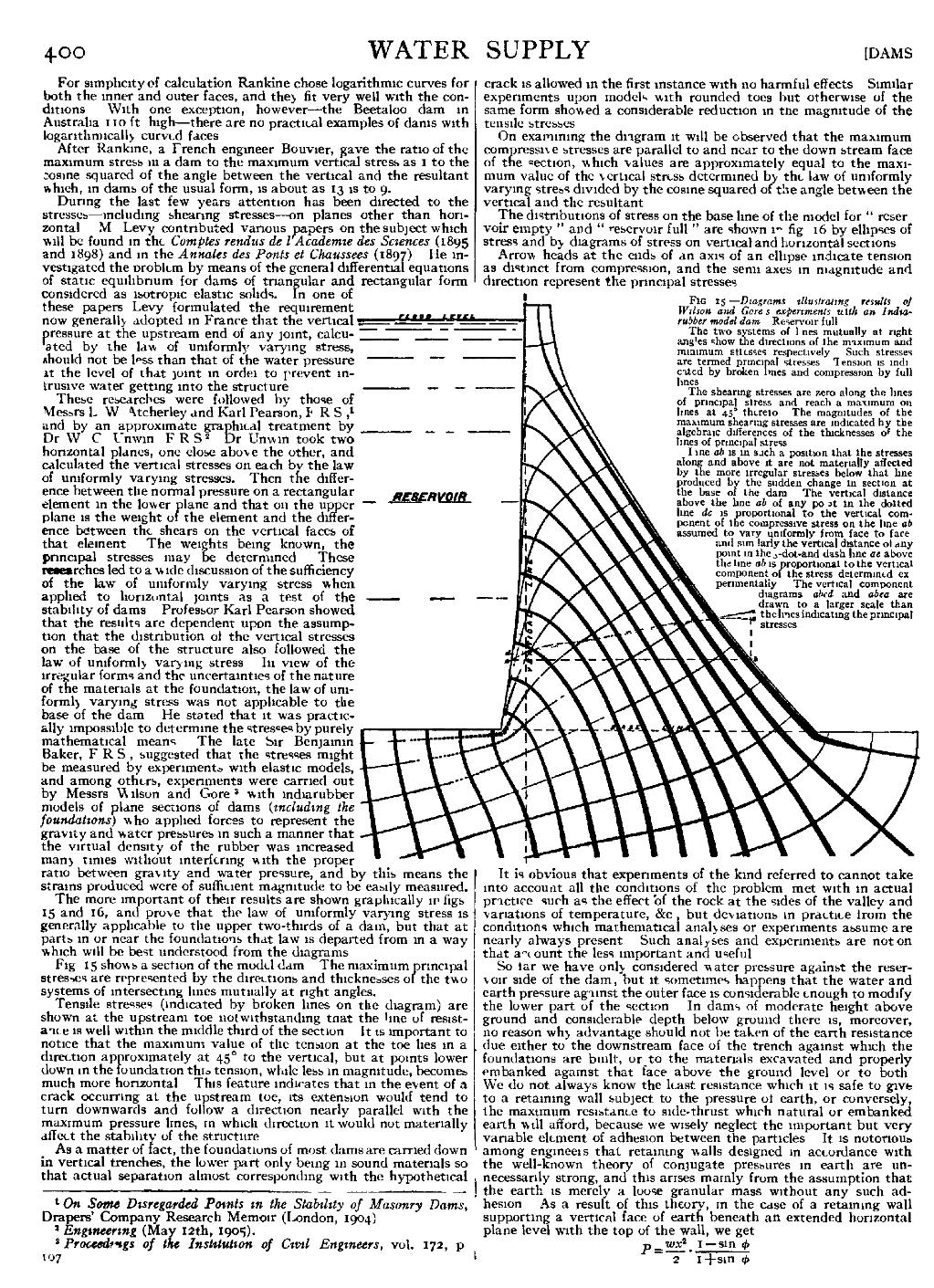
The more important of their results are shown graphically in figs. 15 and 16, and prove that the law of uniformly varying stress is generally applicable to the upper two-thirds of a dam, but that at parts in or near the foundations that law is departed from in a way which will be best understood from the diagrams.
Fig. 15 shows a section of the model dam. The maximum principal stresses are represented by the directions and thicknesses of the two systems of intersecting lines mutually at right angles.
Tensile stresses (indicated by broken lines on the diagram) are shown at the upstream toe notwithstanding that the line of resistance is well within the middle third of the section. It is important to notice that the maximum value of the tension at the toe lies in a direction approximately at 45° to the vertical, but at points lower down in the foundation this tension, while less in magnitude, becomes much more horizontal. This feature indicates that in the event of a crack occurring at the upstream toe, its extension would tend to turn downwards and follow a direction nearly parallel with the maximum pressure lines, in which direction it would not materially affect the stability of the structure.
As a matter of fact, the foundations of most dams are carried down in vertical trenches, the lower part only being in sound materials so that actual separation almost corresponding with the hypothetical crack is allowed in the first instance with no harmful effects. Similar experiments upon models with rounded toes but otherwise of the same form showed a considerable reduction in the magnitude of the tensile stresses.
On examining the diagram it will be observed that the maximum compressive stresses are parallel to and near to the down stream face of the section, which values are approximately equal to the maximum value of the vertical stress determined by the law of uniformly varying stress divided by the cosine squared of the angle between the vertical and the resultant.
The distributions of stress on the base line of the model for “reservoir empty” and “reservoir full” are shown in fig. 16 by ellipses of stress and by diagrams of stress on vertical and horizontal sections.
Arrow heads at the ends of an axis of an ellipse indicate tension as distinct from compression, and the semi-axes in magnitude and direction represent the principal stresses.

It is obvious that experiments of the kind referred to cannot take into account all the conditions of the problem met with in actual practice, such as the effect of the rock at the sides of the valley and variations of temperature, &c., but deviations in practice from the conditions which mathematical analyses or experiments assume are nearly always present. Such analyses and experiments are not on that account the less important and useful.
So far we have only considered water-pressure against the reservoir side of the dam; but it sometimes happens that the water and earth pressure against the outer face is considerable enough to modify the lower part of the section. In dams of moderate height above ground and considerable depth below ground there is, moreover, no reason why advantage should not be taken of the earth resistance due either to the downstream face of the trench against which the foundations are built, or to the materials excavated and properly embanked against that face above the ground level or to both. We do not always know the least resistance which it is safe to give to a retaining wall subject to the pressure of earth, or conversely, the maximum resistance to side-thrust which natural or embanked earth will afford, because we wisely neglect the important but very variable element of adhesion between the particles. It is notorious among engineers that retaining walls designed in accordance with the well-known theory of conjugate pressures in earth are unnecessarily strong, and this arises mainly from the assumption that the earth is merely a loose granular mass without any such adhesion. As a result of this theory, in the case of a retaining wall supporting a vertical face of earth beneath an extended horizontal plane level with the top of the wall, we get